Edwards Signaling 5536MHV-24 User Manual
Page 2
P/N 3100009 ISSUE 2
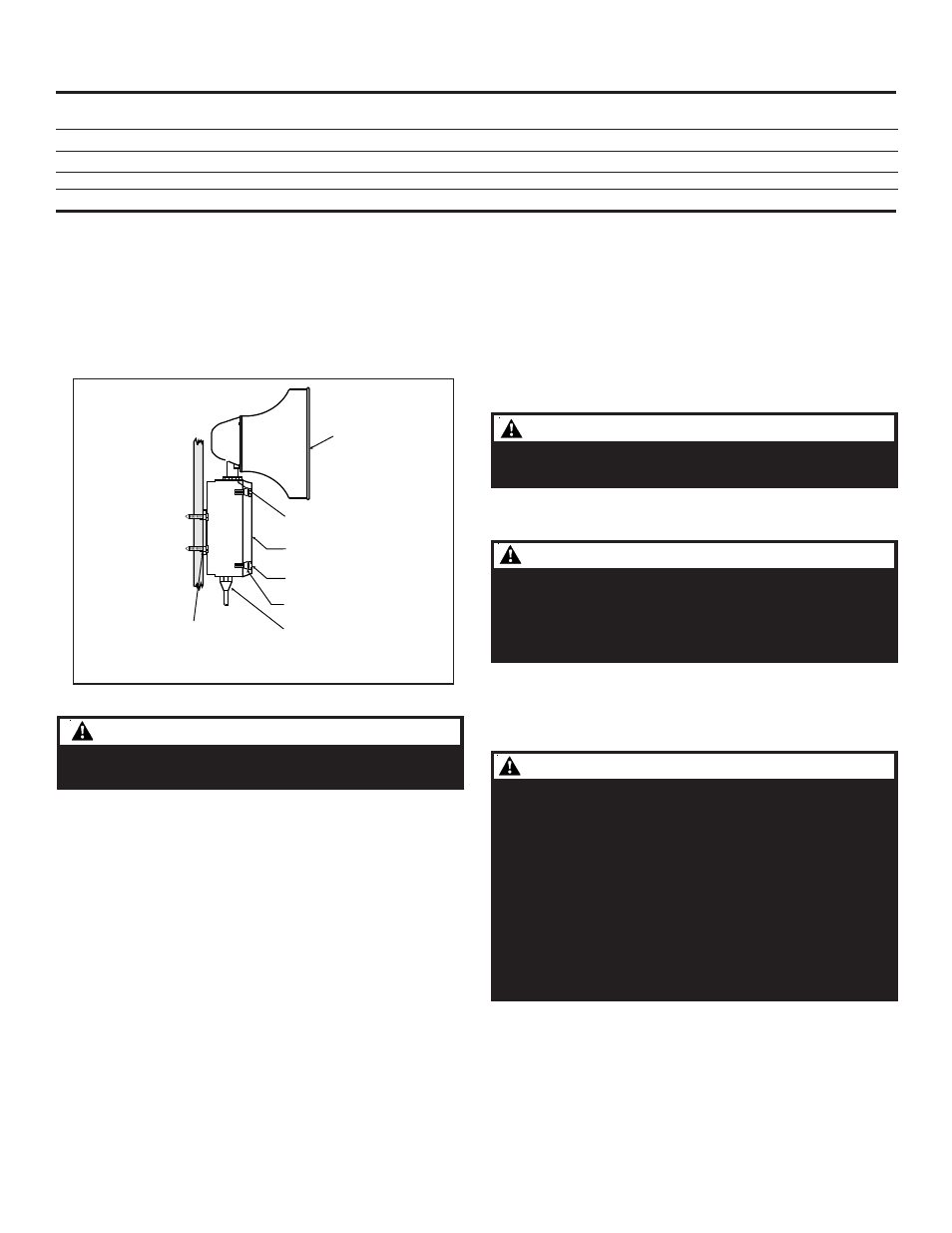
Speaker
Large star nut to
adjust speaker
direction
Signal Box
(4) Cover
screws
(4) Collar
gaskets
Raceway and connections
(not supplied) to
1/2" (12.7 mm) knockout
hole
(4) #10 x 3" (76 mm)
screws or other hardware
suitable for the mounting surface
2. Install wires through a knockout hole in the bottom
of the box from a raceway that is, with its connections
to the 1/2" (12.7 mm) conduit knockout hole, approved
for the same degree of protection and enclosure type
needed by the application. Use the provided plastic
tie-wrap, on the barrier to the electronics, to separate
incoming power leads from signal and tone initiating
leads, per NEC (Figure 3).
5. Adjust volume level, if desired, by turning
potentiometer located on the main board (Figure 9).
Figure 2. Adaptatone Mounting
3. Wire as follows:
a. Connect green and yellow striped earth-ground
wire to earth-ground.
b. Select the appropriate method for wiring to the
input board (Figure 9) from Figures 5 - 10. Connect
the Adaptatone as shown.
c. Connect incoming power to wire leads using a
butt splice or other method listed, certified, or
otherwise approved by local authorities. Leads
are both black for -AQ and -N5 models and are
black for line and white for neutral for -Y6 models.
d. Optional. Connect external 24V DC battery (not
supplied) in series with separate diode assembly
part 2600010 (supplied) to TB1 terminals 3 and 4
on the main board as shown in Figure 4 and
marked on the diode assembly.
NOTE: Terminal Block TB1 can be unplugged from the
main board to complete wiring as shown in
Figure 4.
WARNING
WARNING
WARNING
WARNING
WARNING
To prevent fire and shock, wire the Adaptatone only as
described in this installation instruction.
4. Refer to Figures 9 and 11 and select desired tones. Set
the miniature programming switches on the input
board.
For input connected to IN2, set on SW2; IN3, set on
SW3; IN4, set on SW4, in order of priority desired.
NOTE: Connection to IN1 is factory wired from Audio
Input Board for the external audio signal and
has priority over other signals when activated by
the 24V DC priority signal (Figures 7 and 8).
6. To adjust speaker direction, loosen large star nut
(Figure 2) and turn speaker to the approximate desired
position. Retighten nut and turn speaker slightly
clockwise until locked into place.
7. Tightly secure the signal box cover using (4) retained
cover screws.
8. Torque signal box cover screws to a minimum of 20
in-lbs.
9. Verify operability.
Table 1. Programming Logic Controller (PLC) Compatibility: PLC output to meet following product input
parameters. See Figure 10.
Operating voltage
Max. off state
Continuous on current
Surge (inrush/duration)
Cat. No.
(Volts*)
leakage current (mA)
(mA)
(Amps/milliseconds)
5536M-24AQ
24V DC only
2
740
8/4
5536M-24N5
120V 60 Hz
2
360
2.82/4
5536MHV-24AQ
24V DC only
2
1500
8/4
Input Board Circuit
24V DC
2
6
--
W A R N I N G
W A R N I N G
W A R N I N G
W A R N I N G
W A R N I N G
HIGH VOLTAGE is present when product is energized. High
volume may cause harm to personnel in close proximity.
WARNING
WARNING
WARNING
WARNING
WARNING
To ensure integrity of the enclosure: Ensure the cover
gasket, part number P-007549-0069, is adhered into
groove at cover perimeter before replacing the signal box
cover.
Ensure that the (4) collar gaskets, part number P-041930-
0362, are in place on each cover screw before securing the
signal box cover.
When securing cover, start screws by hand, making sure
they are threaded into tapped holes in housing bosses
before securing with a screwdriver. Torque signal box cover
screws to a minimum of 20 in-lbs. This ensures the
required tight fit.
WARNING
WARNING
WARNING
WARNING
WARNING
To ensure integrity of the Adaptatone assembly when
adjusting the speaker direction, make sure threads in the
enclosure remain fully engaged and do not turn speaker
more than 360 degrees from the original factory installed
position.
Page 2