Edwards Signaling 105XBRi Series User Manual
Page 4
P/N 3101612 ISSUE 3
6. Wire the beacon as follows (Figure 5).
a. For AC models: There are four 24" wire leads: white
(AC neutral), red (for activation of red LEDs), blue with
green tracer (for activation of green or blue LEDs--
depending on the model) and amber (for activation of
amber LEDs). Using wire nuts, connect white lead to
AC neutral and connect each of the other three leads
to AC hot (120V AC) source.
b. For DC models: There are four 24" wire leads: black
(DC -), red (for activation of red LEDs), blue with
green tracer (for activation of green or blue LEDs--
depending on the model), and amber (for activation
of amber LEDs). Using wire nuts, connect black lead
to DC - and connect each of the other three leads to
DC + (24V DC) source.
7. The 105XBRi Multi-Status indicator is shipped with
XTRA-SAFE
TM
Technology Enabled. The unit offers two
other field selectable options: (1) for applications without
a separate PLC or controller with the XTRA-SAFE
TM
Technology disabled or (2) for applications with a separate
PLC or controller. For more information on the features,
refer to the description. For settings, refer to Figure 4.
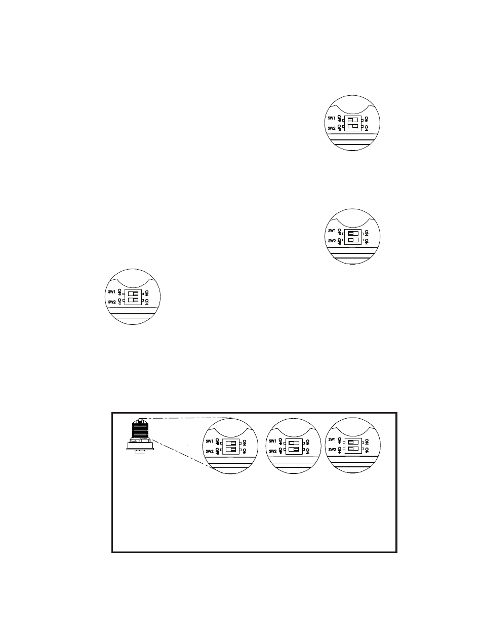
b. Set dipswitches for desired options (Figure 4)
- Applications without a separate PLC or
Controller - XTRA-SAFE Technology Disabled:
Set dipswitch SW1 to the OFF position and SW2
to the ON position.
XTRA-SAFE Enabled
XTRA-SAFE Disabled
With a PLC or other External Controller
Figure 4. Dipswitch Settings
Applications WITH
a PLC or Controller*
Applications WITHOUT
a PLC or Controller* -
XTRA-SAFE Technology
Disabled
Applications WITHOUT
a PLC or Controller* -
XTRA-SAFE Technology
Enabled
(Factory Default)
*It is generally recommended that both dipswitches, SW1 and SW2,
be set to OFF for applications using an external Programmable Logic
Controller (PLC) or other external controller. A PLC or controller, how-
ever, can be used with any of the shown configurations.
a. Unscrew the lens from the bottom of base (Figures 1
and 2) and remove lens.
- Applications with a separate PLC or Controller - Set
dipswitches SW1 and SW2 to the OFF position.
8. Ensuring that the light source is in place, screw the lens
back on the base.
9. Apply power and verify operability.