Detcon MCX-32-N4X User Manual
Page 28
Model MCX-32
Model MCX-32 Instruction Manual
Rev.2.3
Page 22 of 49
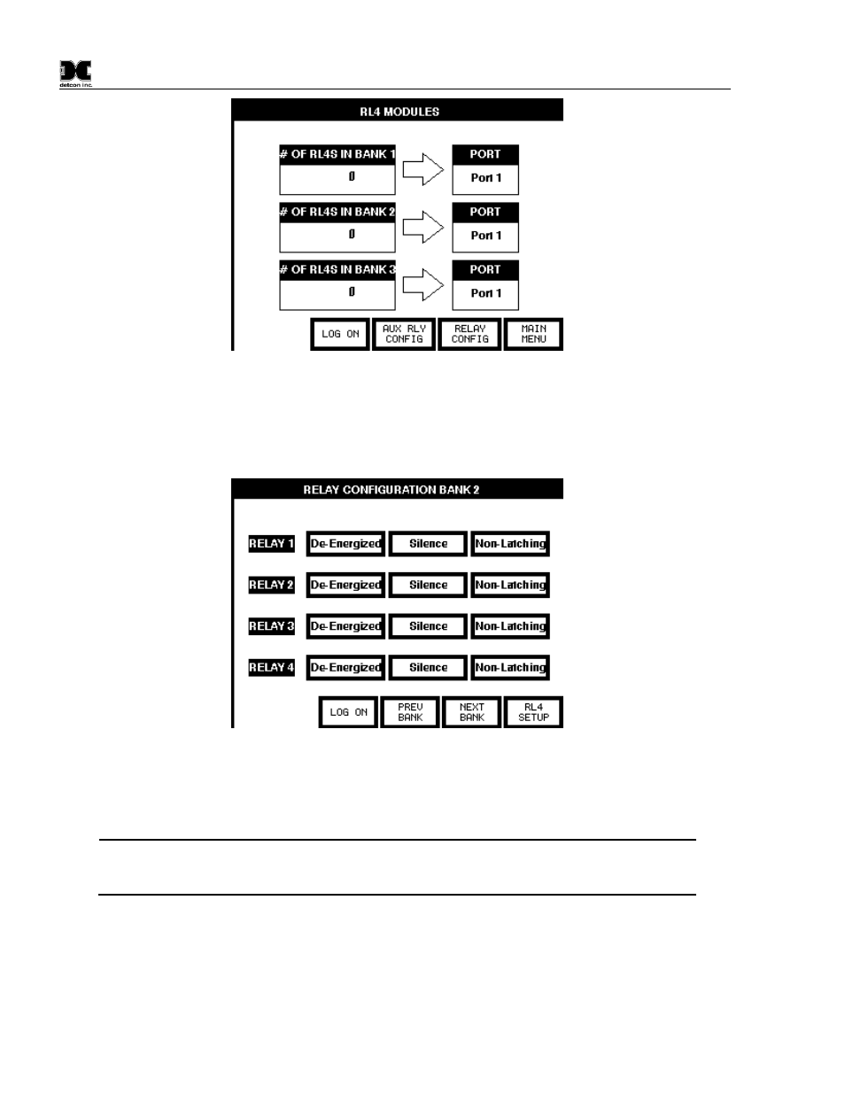
Figure 18 RL-4 Setup Screen
Each RL-4 module consists of four relays. To configure these relays, select the ‘RELAY CONFIG’ button at
the bottom of the RL4 Setup screen. All four relays will be displayed for each bank. Selecting the ‘RL4
SETUP’ button will return to the RL4 Setup screen, and selecting ‘NEXT BANK’ will go to the next bank,
selecting ‘PREV BANK’ will go to the previous bank, where the same parameters can be set for that bank.
Figure 19 Relay Bank Configuration
Each relay within the bank can be set as Energized/De-energized, Silence-able/Non-Silence-able, and
Latching/Non-latching. Selecting the appropriate field will toggle that field between the two selections. Refer
to Section 4.4 Alarm Relay Outputs (RL-4) for more information on these settings.
NOTE: There are three ‘banks’ of alarm relays. The ‘bank’ of relays that a specific sensor is
assigned to is selected from that sensor’s Channel Details screen. This screen also allows
assigning alarm set points, and whether the set point is ascending or descending.
Auxiliary Relays
The Interface PCA contains two relays that can be configured and used for contact closure outputs for
‘FAULT’ and ‘NO-COMM’. The Fault Relay is set whenever there is a sensor fault, and the No-Comm relay
is set when there is a no communication error. Wiring to these relays should be brought directly to the
Interface PCA. The Terminal Blocks on the Interface PCA are labeled NO1, C1, and NC1 for the NO-COMM
relay, and NO2, C2, and NC2 for the FAULT relay. (NO – Normally open Contact, C – Common Contact,