Alarm relay outputs (rl-4), Figure 9 model rl-4 relay output module, 4 alarm relay outputs (rl-4) – Detcon MCX-32-N4X User Manual
Page 18: Fault device alarm 2 device
Model MCX-32
Model MCX-32 Instruction Manual
Rev.2.3
Page 12 of 49
Details screen.
After identifying the correct port and address for the AO-4 module, the ‘Analog Out’ must be turned ‘ON’
from the Channel Details screen for the specific channel corresponding to the AO-4’s output. A properly
addressed AO-4 that is correctly connected and configured to the controller will respond to channel activation
with a 4-20mA output reading equal to the current concentration reading reported to the controller for the
associated channel.
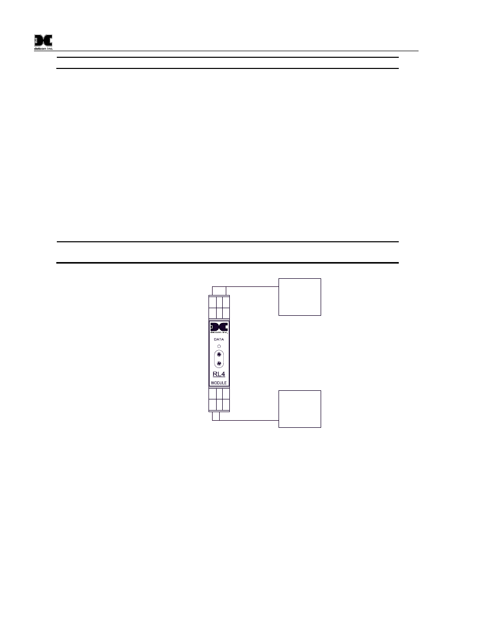
4.4 Alarm Relay Outputs (RL-4)
There are four Form C, Single Pole Double Throw (SPDT), 5 Amp relay contacts in each Model RL-4 module.
Each relay in the module is assigned specifically to one alarm. Relay 1 is assigned to Alarm 1, relay 2 is
assign to Alarm 2, relay 3 is assigned to Alarm 3, and relay 4 is assigned to Fault. These can be used to
control (fire) annunciating devices or as signal inputs to other control devices. Connections to the relay
contacts of the RL-4 module are shown in Figure 9 and are labeled C (Common), NO (Normally Open) and
NC (Normally Closed). Note that the 5 Amp rating of the relay contact should not be exceeded. RL-4
modules can be installed on the DIN rail of the controller.
NOTE: The current ratings of the relay contacts should not be exceeded. (5A @ 30VDC, 5A
@ 250VAC)
RELAY
COMM
M
S
D
L
S
D
Alarm 1
Alarm 2
Alarm 3
Fault
Relay 4
Relay 3
Relay 1
Relay 2
There are four relay
contact outputs on
each RL-4 module.
NC
C
NO
NC
C
NO
C
NC
NO
C
NC
NO
Fault
Device
Alarm 2
Device
Figure 9 Model RL-4 Relay Output Module
RL-4 modules provide a contact output for the associated channel. These outputs are communicated by the
controller to the RL-4 modules using RS-485 Modbus™ RTU protocol therefore each RL-4 module must have
a unique Modbus™ address. Modules are serially addressed in hex using the two rotary switches on the
module’s front panel labeled MSD (most significant digit) and LSD (least significant digit). RL-4 modules
can be connected to either Port 1 or Port 2 of the controller. For the controller to recognize the modules, the
port that the modules are connected to must be set in the RL4 Setup screen (see section 6.3.2), and must match
the physical port that they are attached to for proper communication. Once the relay modules have been
addressed and installed on the Modbus™, the controller can communicate with the RL-4’s. For correct
communication with an RL-4, the RL-4 must have a valid address, the bank that the RL-4 is addressed in must
have that RL-4 enabled in the bank, and the RL-4 must be connected to the correct port (as prescribed on the
RL4 Setup screen).