General wiring notes, Initial start-up, Compactflash card – Detcon MCX-32-N4X User Manual
Page 22: Figure 12 interface pca, 9 initial start-up
Model MCX-32
Model MCX-32 Instruction Manual
Rev.2.3
Page 16 of 49
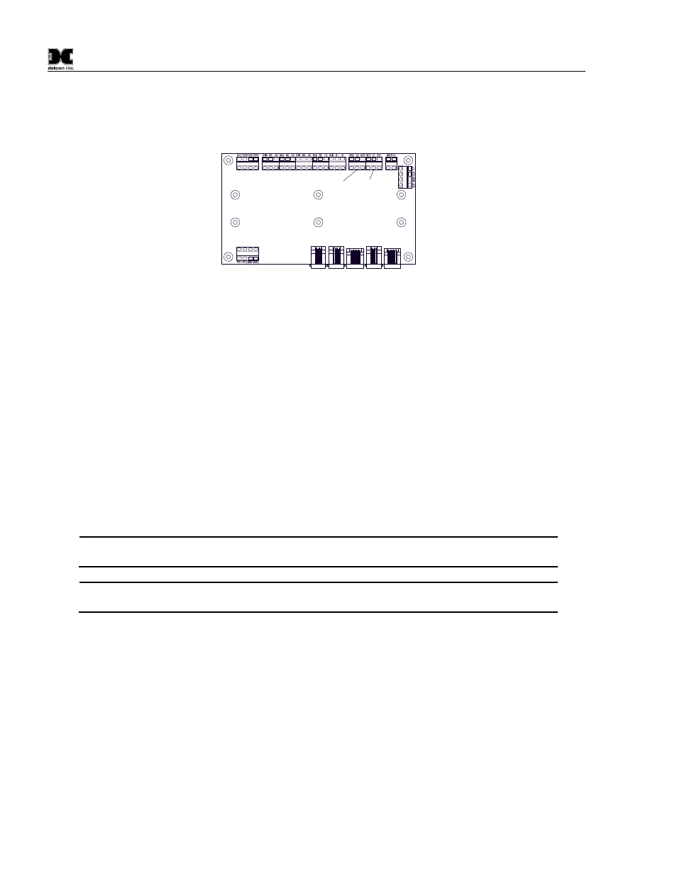
labeled NO1, C1, and NC1 for the NO-COMM relay, and NO2, C2, and NC2 for the FAULT relay. (NO –
Normally open Contact, C – Common Contact, and NC – Normally Closed Contact.) These relays may be
setup as Energized or De-energized, Silence or Non Silence, and Latched or Unlatched, refer to section 6.3.2
RL4 Setup Screen for the configuration of the relays.
PORT 1
PORT 2
PORT 3
PORT 4
PORT 5
FAULT
NO-COMM
Figure 12 Interface PCA
4.8 General Wiring Notes
Follow generally accepted guidelines for RS-485 serial networks. Do not wire I/O Modules and/or
Modbus™ gas sensors in long-distance ‘T-Tap’ configurations.
Instead, use a “daisy-chain” wiring
scheme.
Use Detcon Recommended cabling whenever possible.
General Cable Commodore p/n ZO16P0022189 is recommended for a single cable providing
serial communications and power.
Ground the cable shielding at the Model MCX-32 controller only. Other points of grounding may cause a
ground loop, and induce unwanted noise on the RS-485 line, which in turn may disrupt communications.
4.9 Initial Start-Up
The MCX-32 controller will power up as soon as power is applied. There is no external power switch to the
unit.
NOTE:
Before applying power, check to make sure that all the wiring connections and
external devices are installed correctly.
NOTE:
Applying power with devices hooked up incorrectly may cause damage to the
equipment.
When power is applied to the unit, the unit will boot up and run various initialization steps. It will proceed to
poll Modbus™ addresses of any attached devices and will display their associated channels.
This is
considered normal operation.
If a previous configuration does not exist, the user will need to run the auto configuration function or manually
configure the network from the user-interface. After the unit has been configured, the unit will begin normal
operation. If the unit has been configured properly, the unit will display the current status of the devices that it
is connected to.
5.0
CompactFlash Card
The MCX-32 controller has a feature that allows data logging when a CompactFlash (CF) memory card is
installed. The CF card must be installed in the CF slot located on the back of the controller’s display unit
before the controller is powered up. The controller will automatically format the card and create the necessary