Table 2 ao-4 modbus™ addresses – Detcon MCX-32-N4X User Manual
Page 17
Model MCX-32
Model MCX-32 Instruction Manual
Rev. 2.3
Page 11 of 49
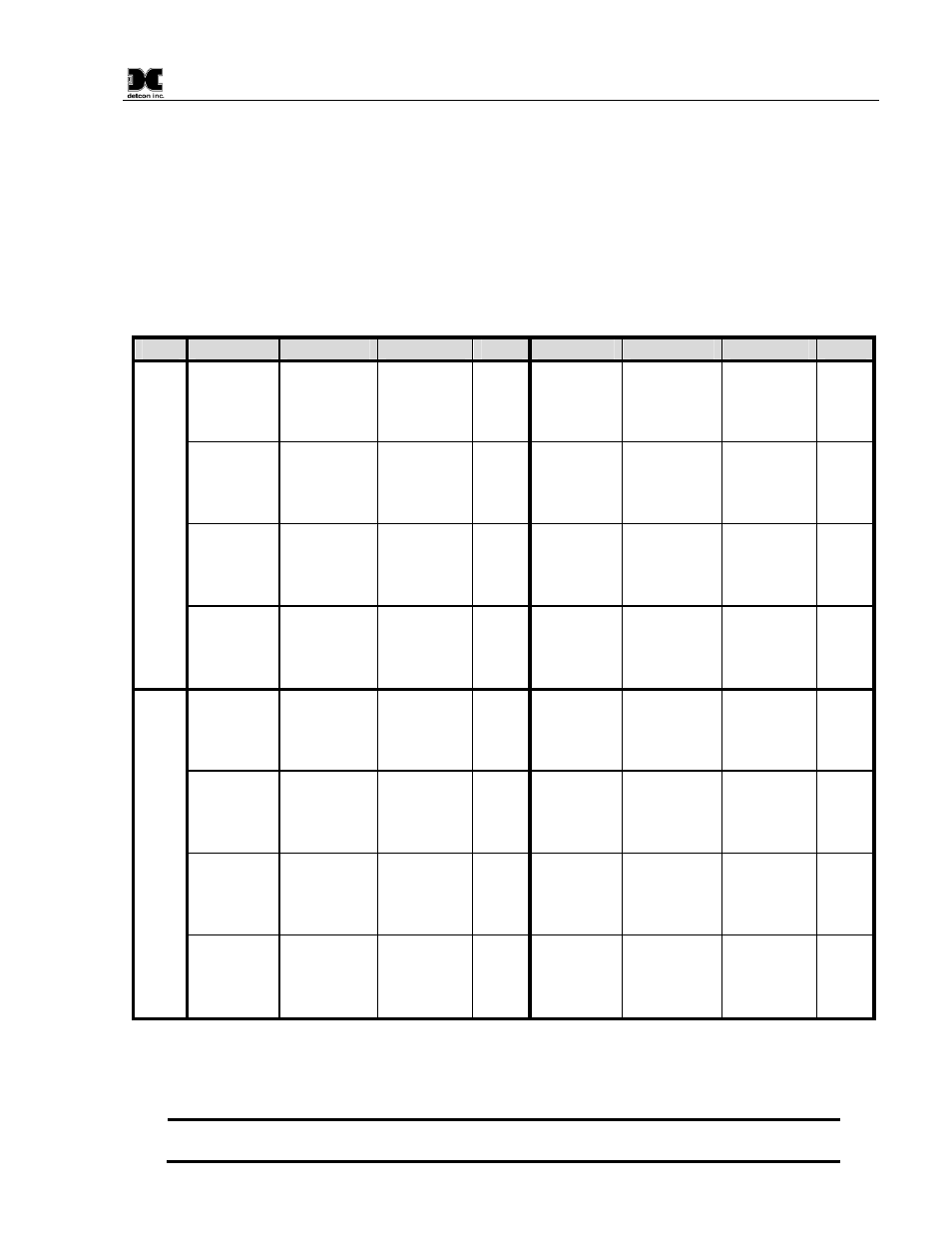
As an example, assume all 64 channels from the MCX-32 have sensors configured to them and the sensor
reading of channel 39 is wanted as an input to another control device. First note that channel 39 corresponds
to module 10 in Port 2 with hex address A9 per Table 2. Therefore, an AO-4 module set to hex address A9
would need to be installed in Port 2 of the MCX-32. Next, the ‘Analog Out’ on the Channel Details screen for
channel 39 would need to be turned ‘ON’. The MCX-32 would now be able to recognize the AO-4 module
and the module’s DATA COMM LED would blink intermittently, indicating a valid communication status.
The AO-4 module would output a 4-20mA signal on its output 3 (Figure 8) corresponding to channel 39’s
reading.
Table 2 AO-4 Modbus™ Addresses
Port
Module
Channel #
Decimal
Hex
Module
Channel #
Decimal
Hex
1
1
1
2
3
4
160
A0
2
5
6
7
8
161
A1
3
9
10
11
12
162
A2
4
13
14
15
16
163
A3
5
17
18
19
20
164
A4
6
21
22
23
24
165
A5
7
25
26
27
28
166
A6
8
29
30
31
32
167
A7
2
9
33
34
35
36
168
A8
10
37
38
39
40
169
A9
11
41
42
43
44
170
AA
12
45
46
47
48
171
AB
13
49
50
51
52
172
AC
14
53
54
55
56
173
AD
15
57
58
59
60
174
AE
16
61
62
63
64
175
AF
An AO-4 module connected properly to the controller will have a flashing DATA COMM LED to indicate a
valid communication status and will provide a 4-20mA output equal to the current concentration reading
reported to the controller for the associated channel.
NOTE: AO-4 modules can be connected to either Port 1 or Port 2, they must be addressed
correctly, and their associated channel’s ‘Analog Out’ must be turned ‘ON’ from the Channel