2 replacement of intelligent plug-in sensor, Replacement of intelligent plug-in sensor, Figure 26 replacing the cap – Detcon PI-700 0-500ppb User Manual
Page 37: Figure 27 sensor assembly
Model PI-700 0-500ppb
PI-700 0-500ppb Instruction Manual
Rev. 0.0
Page 33 of 53
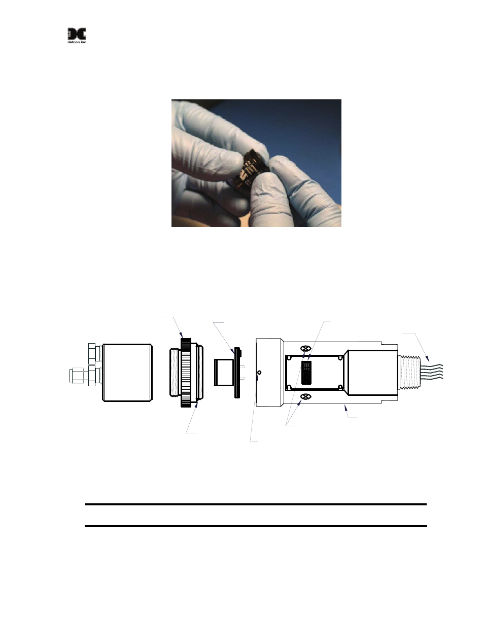
6. Align the Cap Key with the notch on the housing. Starting at the side opposite the notch, press down until
the Filter Cap snaps on to the housing. If the Cap Key is incorrectly aligned there will be a noticeable
bulge on the side of the cap.
Figure 27 Replacing the Cap
Visual Inspection
The Sensor should be inspected annually. Inspect for signs of corrosion, pitting, and water damage. During
visual inspection, the Sample Chamber should be inspected to insure that it is not blocked. Examine the plug-
in sensor for signs of physical blockage, electrolyte leakage, or severe corrosion. Also, inspect inside the
Junction Box for signs of water accumulation or Terminal Block corrosion.
O-Ring
Sample
Chamber
Housing Bottom
Locking Set-Screw
Intelligent Transmitter Module
(ITM)
Micro-processor controlled circuitry
enclosed in an explosion-proof
housing
MOD
E
L
PI-
700
PG
M
2
S
PAN
VOC
de
tc
on in
c.
Replaceable Intelligent
Plug-in Sensor
ZER
O
PGM
1
Interconnect Wires
Magnetic Programming
Switches
Lens and LED Display
SS Splash
Guard
Adapter
Figure 28 Sensor Assembly
5.2 Replacement of Intelligent Plug-in Sensor
NOTE: It is not necessary to remove power while changing the Intelligent plug-in VOC gas
sensor in order to maintain area classification, since it is intrinsically safe.
a) Use a 1/16” Allen wrench to release the locking setscrew that locks the ITM and Splash Guard Adapter
together (One turn will suffice - Do not remove setscrew completely).
b) Unthread and remove the Splash Guard Adapter and Sample Chamber from the ITM.