Service and maintenance, 1 pid plug-in sensor maintenance, Pid plug-in sensor maintenance – Detcon PI-700 0-500ppb User Manual
Page 31: Figure 12 uv lamp aging expectation
Model PI-700 0-500ppb
PI-700 0-500ppb Instruction Manual
Rev. 0.0
Page 27 of 53
5. Service and Maintenance
Calibration Frequency
In most applications, quarterly span calibration intervals will assure reliable detection. However, industrial
environments differ. Upon initial installation and commissioning, close frequency tests should be performed,
weekly to monthly. Test results should be recorded and reviewed to determine a suitable calibration interval.
If, after 180 days, an AutoSpan Calibration is not performed, the ITM will generate an AutoSpan Fault.
5.1 PID Plug-In Sensor Maintenance
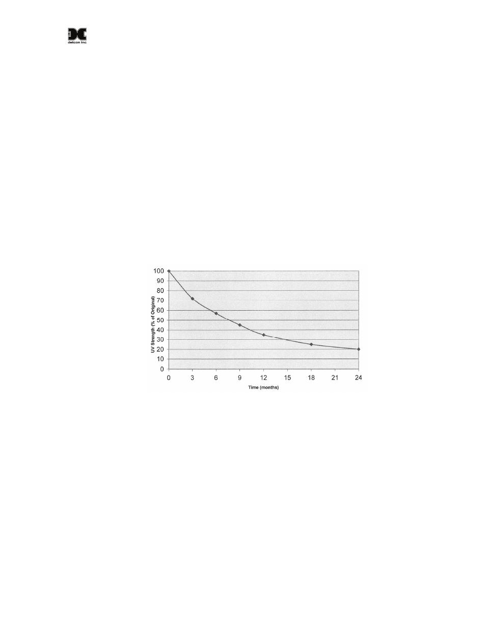
The plug-in PID Sensor will need to be properly maintained to achieve proper long-term performance. All
PID sensors use a UV lamp that has a finite lifetime. The Detcon PID UV lamp source is expected to last at
least 1 year. However, from the time of installation a gradual loss in UV lamp strength is expected (Figure
13). As the UV lamp strength decreases the sensor signal will decrease accordingly. This dictates that
periodic span calibrations are required to maintain calibration accuracy. To determine the present signal
strength of the PID sensor, execute a valid span calibration and view the Sensor Life from the ‘View Program
Status’ menu. Any Sensor Life value less than 30% should result in the user’s choice of replacing the plug-in
sensor, cleaning the UV Lamp, or replacing the UV Lamp.
Figure 13 UV Lamp Aging Expectation
If the PID sensor appears to be losing signal strength at a rate faster than the estimates shown in Figure 13, the
sensor is most likely experiencing contamination film build-up on the UV optical filter. This will happen
when exposed to certain gases or ambient contaminations that collect on the surface of the UV filter. The
result is a decrease in the amount of emitted UV light from the lamp source. This is known to happen with
gases that can be polymerized by UV light (such as heavy complex VOC’s), airborne oil vapors, and very fine
dust. As UV Filter contamination occurs, the sensor’s signal strength falls off in addition to the expected loss
rate shown in Figure 13. This phenomenon can be reversed by disassembling the sensor and carefully cleaning
the UV lamp filter using a specialized cloth.
It is also possible, under certain ambient contamination conditions, that the sensor’s Detector Cell may have a
partially conductive film that forms across the contact grids. This condition causes the zero background signal
to gradually increase to the point where it becomes unacceptable for the range of signal input to the transmitter
electronics. When this occurs the detector cell should be replaced. This can be checked by examining the
amount of raw signal that is produced during exposure to zero gas. Refer to the ‘View Program Status’ menu
and record the Raw Signal report after 5 minutes of zero gas exposure. A value that exceeds 3000 counts
would be evidence of this problem.