4 pressure measurement sequence (gage only unit) – Condec UPC5110 User Manual
Page 9
6
UPC5100/UPC5110 Operation & Maintenance Manual
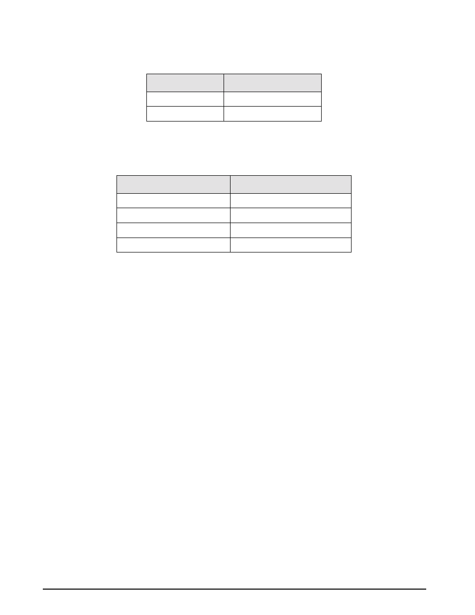
The display scaling for these current measurements are as follows:
NOTE: UPC5100/UPC5110 reads a 4-20 mA signal only, but will display as either 4-20 mA or 20-100 mV.
The test cable connector wiring is as follows:
NOTE: Connector pin designations are for reference only, and are no longer a connector on newer units. See Figure 2-2
on page 5 (14).
2.4
Pressure Measurement Sequence (Gage Only Unit)
NOTE: See Figure 2-3 on page 5 when following these steps:
1. Turn the
MODE SELECT
valve (10) to the
PRESSURE
position.
2. Close the
COARSE ADJUSTMENT
valve (2), clockwise, and open the
VENT
valve (8),
counter-clockwise.
3. Using the
PRESSURE LIMIT CONTROL
regulator (1), (pull knob outward while adjusting) adjust the
maximum system input pressure (as read by the
PRESSURE LIMIT MONITOR
[9]), to any desired value
higher (typically 20-50% higher) than the full-scale range of the device under test. Using this technique,
the device under test is fully protected from being accidentally over-pressurized.
4. Zero unit by momentarily depressing the
ZERO
switch (12) for less than five seconds.
NOTE: The instrument can be zeroed at any time, as long as the VENT valve (8) is open, by momentarily depressing the
ZERO switch (12) for less than five seconds.
5. To apply pressure, close the
VENT
valve (8), approximately two turns clockwise, until it stops, then open
the
COARSE ADJUSTMENT
valve (2) approximately 1/2 turn counter-clockwise until the numerical
display begins to move. The operator may change the pressure rapidly until reaching approximately 90%
of the desired final value.
6. Use either the
COARSE ADJUSTMENT
(2) or
VENT
valve (8) to obtain a specific pressure reading. Both
provide precise control. As the pressure approaches the desired value, the valve being used for control
should be rotated slowly clockwise to its closed position.
7. To obtain exact pressure readings, slowly rotate the
VERNIER
control (13) knob in the direction required
(clockwise to increase pressure) as indicated by the electronic numerical display.
8. The transducer current measurement can be displayed at any time by placing the
DISPLAY SELECT
switch (16) in its
CURRENT
position.
SWITCH POSITION
DISPLAY READING
Current
0-20.000 mA by 0.005 mA
*Voltage
0-100.00 mV by 0.02 mV
Table 2-1. Display Select Switch (16)
CONNECTOR PIN DESIGNATION
FUNCTION
A
+ VDC
B
+ SIGNAL
C
NOT USED
D
VOLTAGE & SIGNAL COMMON
Table 2-2. Transducer Test Cable (PN 55092)