Condec UPC5110 User Manual
Page 33
30
UPC5100/UPC5110 Operation & Maintenance Manual
Installation:
1. Connect and solder the wires onto their respective switch terminals (Table 4-4).
2. Install the switch through the panel rear, align with front panel markings, and secure with mounting nut.
3. Install the switch knob using a .061" hex wrench.
4. Replace CPU if necessary.
5. Install panel/chassis assembly in its enclosure as described in Section 4.2.1 on page 14.
4.2.23
Zero Switch (PN 58886) - Removal and Installation
Tools required:
Phillips screwdriver
11/16" open end wrench
A/R soldering iron
Removal:
1. Disconnect the power cord from the power source and line filter. Remove front panel from its enclosure
as described in Section 4.2.1 on page 14, and carefully set on a bench top.
2. Loosen the switch mounting nut and lock washer from the rear of panel.
3. Loosen and remove the trim ring from the panel front.
4. Remove switch, lock washer and nut from rear of panel.
5. Unsolder and remove the wires from the switch terminals.
Installation:
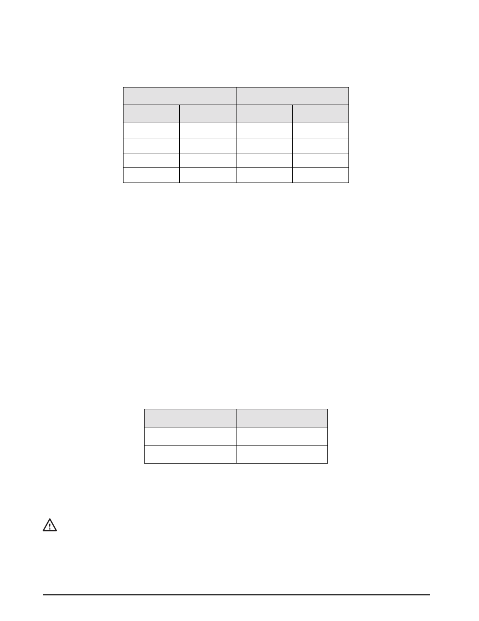
1. Connect and solder the wires onto their respective switch terminals per Table 4-5 below:
2. Install the new switch, lock washer and nut through the panel rear. Hand tighten the trim ring from front
of panel.
3. Tighten the switch mounting nut and lock washer from the rear of panel.
If wrench is used, do not over tighten, damage may occur to switch.
4. Install panel/chassis assembly in its enclosure as described in Section 4.2.1 on page 14.
Range Select:
Display Select:
Pole - Terminal
Color
Pole - Terminal
Color
1 - 3
Yellow
2 - 2
Red
1 - 6 (common)
Red
2 - 3
Blue
2 - 3
Orange
2 - 6 (common)
Green
3 - 4
Brown
Table 4-4. Range Select and Display Select Wire Colors/Switch Terminals
Color
Terminal
Yellow
Normally open
Green
(C) common
Table 4-5. Wire to switch terminal connections: Zero
Caution