0 calibration, 1 pneumatic calibration set-up, 2 instrument calibration set-up – Condec UPC5110 User Manual
Page 12
Calibration
9
3.0
Calibration
Follow the procedure on the following pages for calibrating the UPC5100/UPC5110.
NOTES:
•
When calibrating, the computer within the UPC5100/UPC5110 is actually being re-programmed, therefore it is important that
the pressure standard being used is in satisfactory operating condition and that the technician fully understands its operating
characteristics and methods of usage. In addition, the UPC5100/UPC5110 itself must be properly warmed up (approximately
thirty minutes) and electrically stabilized prior to performing a calibration cycle.
•
The CONDEC Repair Lab is equipped to do calibrations on CONDEC calibrators and pressure standards. Calibrations include a
certification and are traceable to N.I.S.T (see “UPC5100/UPC5110 Return Material Authorization Form” on page 52).
3.1
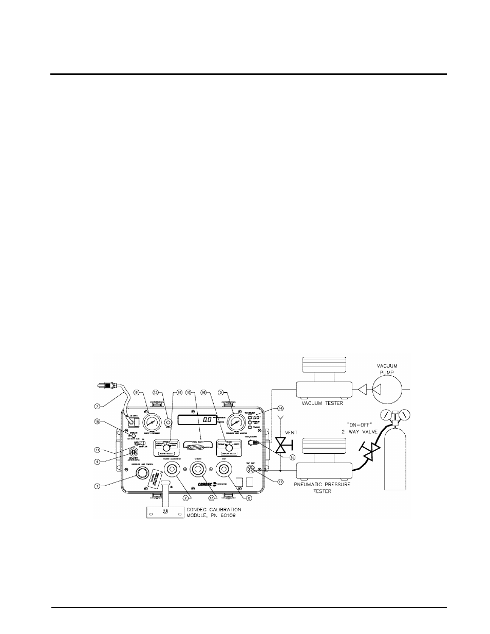
Pneumatic Calibration Set-up
Figure 3-1 defines a typical calibration set-up using a floating piston-type, air dead weight tester and a vacuum
dead weight tester. A vacuum pump will be required to enable calibrating the -14 PSIG of the Bi-directional
ranges.
NOTE:
Any type of precision standard is acceptable as long as its basic accuracy is ±0.025% of point or better.
To permit proper calibration, at least an
ON/OFF
and a
VENT
valve (connected as shown in Figure 3-1) must be
provided.
3.2
Instrument Calibration Set-up
The UPC5100/UPC5110 is placed into its calibrate mode by connecting a Condec Calibration Module (PN
60109) via the multi-pin jack. The jack is located behind the small slide plate near the fill port (see Figure 3-1).
The Condec Calibration Module provides access to the calibrator’s various program modes via a five-position
rotary switch. It also provides a means of entering and storing data via four other momentary action switches.
In the calibrate mode, the UPC5100/UPC1010’s numerical display is used to provide operator prompting
symbols as well as displaying the various data formats. For example, in Figure 3-2, the data format shown is that
obtained as soon as the
ZERO/SPAN
position of the rotary switch is selected.
Figure 3-1. Instrument Calibration Set-up
NOTE:
UPC5100 shown, AC input and Fill Port are on backside of UPC5110 Rack Mountable Calibrator.