Pro-Cut Warthog User Manual
Page 49
WWW.PROCUTUSA.COM
PG /
Ø49
Remove the cover on the bottom of the bevel gearbox assembly. Replace it with the 50-1148 assembly,
taking care to aim the eight pin connector towards the lathe body. With the lathe unplugged from AC
power, seat the 6 pin connector from the slide sensor, and the 8 pin connector from the lathe's harness.
These are waterproof connectors and they seat firmly. Please make sure the small catch latches over the
post on the top of each connector to ensure a complete connection. Re-power the lathe.
THE GAGE PICK UP MODULE 50-1148
ASSEMBLY
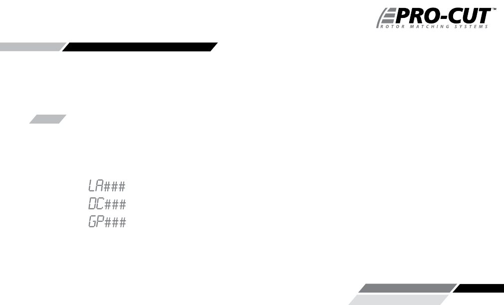
When the lathe is plugged in you will see three letter/number combinations if you have connected every-
thing properly:
The Gage Pickup module also performs cutting detection, but this feature is not used unless you
upgrade to a full Gyr package.
*NOTE:
If the Gage Pickup Module is not connected you will see E.GPM instead of GP###. Always unplug the
lathe when connecting or disconnecting lathe electronics. It is unlikely that doing so while the lathe is
powered will cause any harm, but the electronics work best when they are all powered on and off simul-
taneously.
ELECTRONIC READOUT:
Lathe Adjustment Module & Version Number
(You will see digits, not the # symbol)
Display Control Module & Version Number
Gage Pickup Module & Version Number