Connecting to the host computer – Yokogawa DR240 User Manual
Page 23
3-4
IM DR231-11E
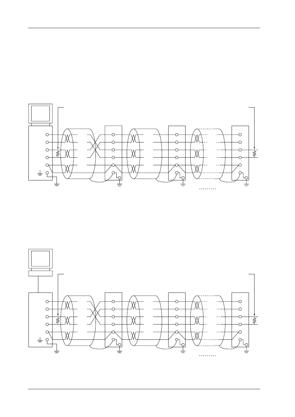
Connecting to the Host Computer
Can be connected to a host computer with RS-232-C, RS-422-A, RS-485 ports.
• In the case of RS-232-C, a converter is used as shown in the diagram below.
• For information on recommended converters, refer to “Converters” in the latter.
• Dip switch needs to be changed depending on whether it is a two-wire system or four-wire sys-
tem. Refer to “3.5 RS-422-A/RS-485 Interface Parameter Setting Procedure.”
In the case of four-wire system
In general, the recorder is wired to the host computer using a four-wire system. When four-wire
system is used, the send and receive wires need to be crossed.
Terminator (externally applied) 120 ohm, more than 1/2 W
#1
No terminators are inserted between #1 through #n-1 (internal OFF)
RS-422-A/RS-485
module
of the DA100/DR
#2
#n
(#n
≤
31)
Terminator (Internal ON)
Host
Computer
SG
RDB( + )
RDA( - )
SDB( + )
SDA( - )
FG
SG
RD B
RD A
SD B
SD A
(SG)
(RD B)
(RD A)
(SDB)
(SDA)
FG
SG
RD B
RD A
SD B
SD A
(SG)
(RD B)
(RD A)
(SDB)
(SDA)
FG
SG
RD B
RD A
SD B
SD A
(SG)
(RD B)
(RD A)
(SDB)
(SDA)
(Diagram below shows the case when the port of the host computer is RS-232-C)
Terminator (externally applied) 120 ohm, more than 1/2 W
#1
No terminators are inserted between #1 through #n-1 (internal OFF)
RS-422-A/RS-485
module
of the DA100/DR
#2
#n
(#n
≤
31)
Terminator (Internal ON)
SHIELD
RD( + )
RD( - )
TD( + )
TD( - )
FG
SG
RD B
RD A
SD B
SD A
Host
Computer
Converter
Z - 101HE
(SHARP)
(SG)
(RD B)
(RD A)
(SDB)
(SDA)
FG
SG
RD B
RD A
SD B
SD A
(SG)
(RD B)
(RD A)
(SDB)
(SDA)
FG
SG
RD B
RD A
SD B
SD A
(SG)
(RD B)
(RD A)
(SDB)
(SDA)
RS-232-C
3.3 RS-422-A/RS-485 Interface Connection