Cable used, Connecting the cable, W title> warning – Yokogawa DR240 User Manual
Page 22
3-3
IM DR231-11E
Overview and Specifications of RS-422-A/RS-485 Interface
3
3.3
RS-422-A/RS-485 Interface Connection
The following explains how the RS-422-A/RS-485 module is connected to the computer.
Cable Used
There are two types of cables: two-wire cable and four-wire cable. Make sure each type meets the
following conditions.
Cable used
: twisted pair shielded cable
2 pairs of 24 AWG minimum (two-wire), 3 pairs 24 AWG mini-
mum (four-wire)
Characteristic impedance
: 100 ohm
Capacitance
: 50 pF/m
Length of cable
: 1.2 km maximum *
* Communication distance of the RS-422-A/RS-485 interface is not the linear distance, but the
total length of the cable (shielded twisted pair cable).
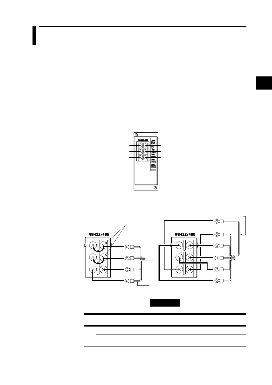
Terminal Arrangement of the RS-422-A/RS-485 Module
RD A Receive data A ( - )
RD B Receive data B ( + )
FG
Frame ground
SD A Send data A ( - )
SD B Send data B ( + )
SG
Signal ground
Screws used for the terminals:
ISO M4 screws, length 6 mm
Connecting the Cable
Attach crimp-on lugs (for 4 mm screws) with insulation sleeves on the leadwire ends as shown in the
diagram below. Make the exposed portion of the shielded cable to be less than 5 cm.
SD/RD A
SD/RD B
SG
FG
Shield potential
For two-wire system
For four-wire system
SD A
FG
SD B
RD B
RD A
SG
Shield
potential
Short the terminals.
<07. W Title>
WARNING
To prevent an electric shock, ensure the main power supply is turned OFF.
Note
• As shown on the next page, connect terminal RD to SD(TD) of the computer (converter) and terminal SD to RD of the
computer.