7. contact output setup – Yokogawa ISC450 4-Wire Analyzer for Inductive Conductivity User Manual
Page 34
26
IM 12D06D05-01E
Expire time
If the output is over 100% for longer than the
expire time, the output will return to 0%.
Damping time
The response to a step input change reaches
approximately 90 percent of its final value
within the damping time.
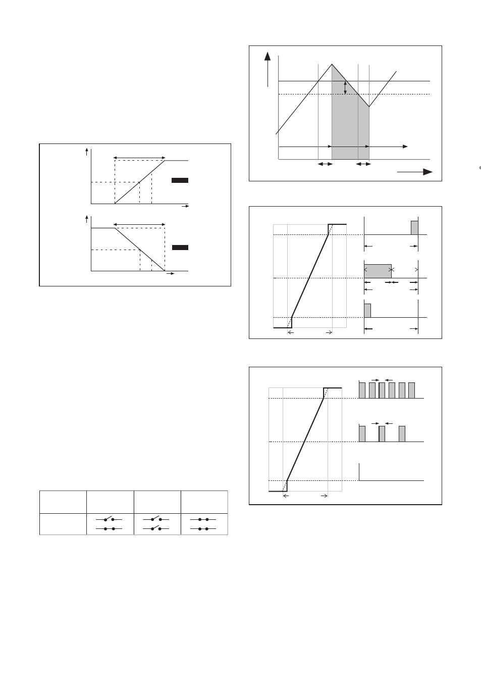
100%
0%
set
point
process
value
Direct
100%
0%
set
point
process
value
Reverse
range
range
manual
reset
manual
reset
Figure 5-2. Direct/Reverse action
5-7. Contact output setup
S1/S2/S3/S4
Each Switch (contact) can have the following
functions.
1. Control : A selection of P- PI- or PID control
2. Alarm : Low or high value Limits monitoring
3. Hold : A hold contact is energised when
the instrument is in HOLD
4. Fail
: S4 is set as fail-safe contact.
6. Simulate : To test the operation of the contact,
simulate can be used. The contact
can be switched on or off or a
percentage of duty cycle can be
entered (DC period time)
7. Off
: Switch is not used.
power on
power on
power down normal opened contact
activated
S1, S2, S3
S4
Above table shows contact output status between common to NO.
Configure hold
Hold is the procedure to set the outputs to
a known state when going into commission-
ing. Du ring commissioning HOLD is always
enabled, out puts will have a fixed or last value.
During ca libra tion the same HOLD function
applies. For ca libra tion, it is up to the user if
HOLD is enabled or not.
Lifetime contacts
One should note that the lifetime of the con-
tacts is limited (10
6
). When these contacts are
used for control (pulse frequency or duty cycle
with small interval times), the lifetime of these
contact should be observed. On/Off control is
preferred over Pulse/duty cycle.
Setpoint
Hys.
SC
off
on
off
Delay time
Delay time
t (sec)
100
50
0
ton
toff
50%
50%
% controller output
Range
Duty cycle
ton > 0.1 sec
Duty cycle
toff > 0.1 sec
Duty cycle
100
50
0
% controller output
Range
0.3 s
Maximum pulse frequency
50% pulse frequency
No pulses
0.3 s
Figure 5-3. Alarm contact (on/off control)
Figure 5-4. Duty cycle control
Figure 5-5. Pulse frequency control