2. wiring, 2-1. preparation, Danger – Yokogawa ISC450 4-Wire Analyzer for Inductive Conductivity User Manual
Page 15: Warning caution warning
7
IM 12D06D05-01E
3
INSTALLATION
AND
WIRING
3-2. Wiring
3-2-1. Preparation
Refer to figure 3-4. The relay contact terminals
and power supply connections are under the
screening (shielding) plate. These should be
connected first. Connect the sensor, outputs
and HART
®
communication connections last.
To open the EXAxt 450 for wiring:
1. Loosen the four frontplate screws and swing
open the cover.
2. The upper terminal strip is now visible.
3. Remove the screen (shield) plate covering
the lower terminal strip.
4. Connect the power supply and contact
outputs. Use the three glands at the back for
these cables.
• Cables that withstand temperatures of at
least 70 °C should be used for wiring.
• Wiring work should be performed to meet
IP66 or higher requirements. Tighten four
frontplate screws to 1.5 N·m torque.
Always place the screen plate over the power
supply and contact terminals for safety reasons
and to avoid interference.
5. Put back (replace) the screen (shield) plate
over the lower terminals.
6. Connect the analog output(s), the sensor
inputs, and, if necessary, the HART
®
wiring
and input contact.
7. Use the front three glands for analog output,
sensor inputs, contact input and HART
®
wiring (see figure 3-5).
8. Swing back the cover and secure it with the
four screws.
9. Switch on the power. Commission the
instrument as required or use the default
settings.
Do not turn on power with the touchcsreen
pressed, otherwise inaccurate screen
positioning will occur. If it occurs, leave the
touchscreen unpressed, turn off power then
on again. The screen positioning will be
accurate.
DANGER
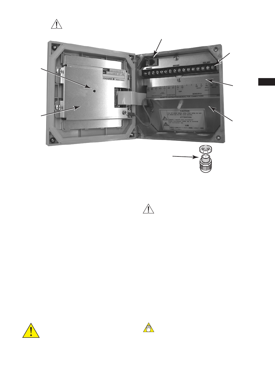
Figure 3-4. Internal view of EXAxt wiring compartment
6 X M20 glands
potentio-
merter
LCD
bracket
connector for (future) software
input
terminal
block
output
terminal
block
protective
shield
bracket
Note: ISC450G-A(D)-U
The enclosure is provided with stoppers in stead of M20 cable glands for the unused holes.
These stoppers must be removed and replaced by FM approved conduit fittings in accord-
ance with good installation practice. See APPENDIX 6, Control drawing for FM approval.
WARNING
CAUTION
WARNING
This connector for software must be used only by
Yokogawa’s service personnel.