Yokogawa ISC450 4-Wire Analyzer for Inductive Conductivity User Manual
Page 21
13
IM 12D06D05-01E
3
INSTALLATION
AND
WIRING
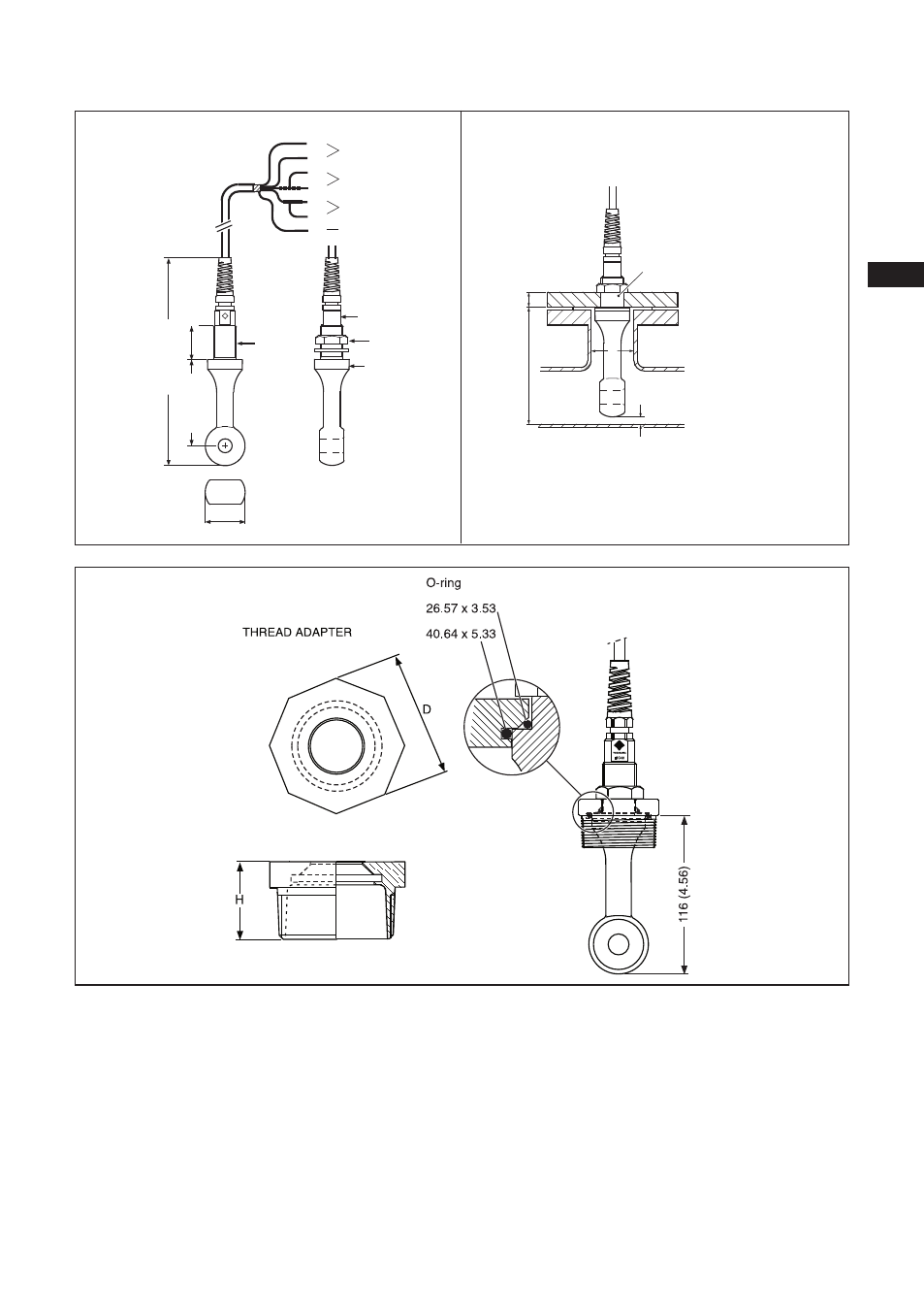
Figure 3-9b. Dimensions
3-6-4. Sensor cable connections using junc-
tion box (BA10) and extension cable
(WF10)
Where a convenient installation is not possible
using the standard cables between sensors and
converter, a junction box and extension cable
may be used. The Yokogawa BA10 junction box
and the WF10 extension cable should be
used. These items are manufactured to a very
high standard and are necessary to ensure that
the specifications of the system can be met.
The total cable length should not exceed 60
metres (e.g. 5 m fixed cable and 55 m exten-
sion cable).
Ø 40 ( 1.57)
wrench opening
20 ( 0.79 )
wrench opening
32 ( 1.42 )
thermistor
ground
secondary
primary
YOKOGAWA
G3/4
47(1.85)
11
12
17
13
15
16
14
L= 5000 ( 200 )
ca 240 (9.45)
40 (1.57)
100 (3.94)
Hole in flange
Ø 27 mm (1.06")
D
d
I
t
d = distance min 25 mm (1")
D = acces port size min 48 mm (1.89")
DIMENSIONS
INSTALLATION INSTRUCTIONS
BULK-HEAD MOUNTING
distance min. 25 mm (1)
access port side min 48 mm (1.89)
UNIT: mm (inch)