2-2. cables, terminals, glands and conduit adapter, Figure 3-5b. how to install cable glands – Yokogawa ISC450 4-Wire Analyzer for Inductive Conductivity User Manual
Page 16
8
IM 12D06D05-01E
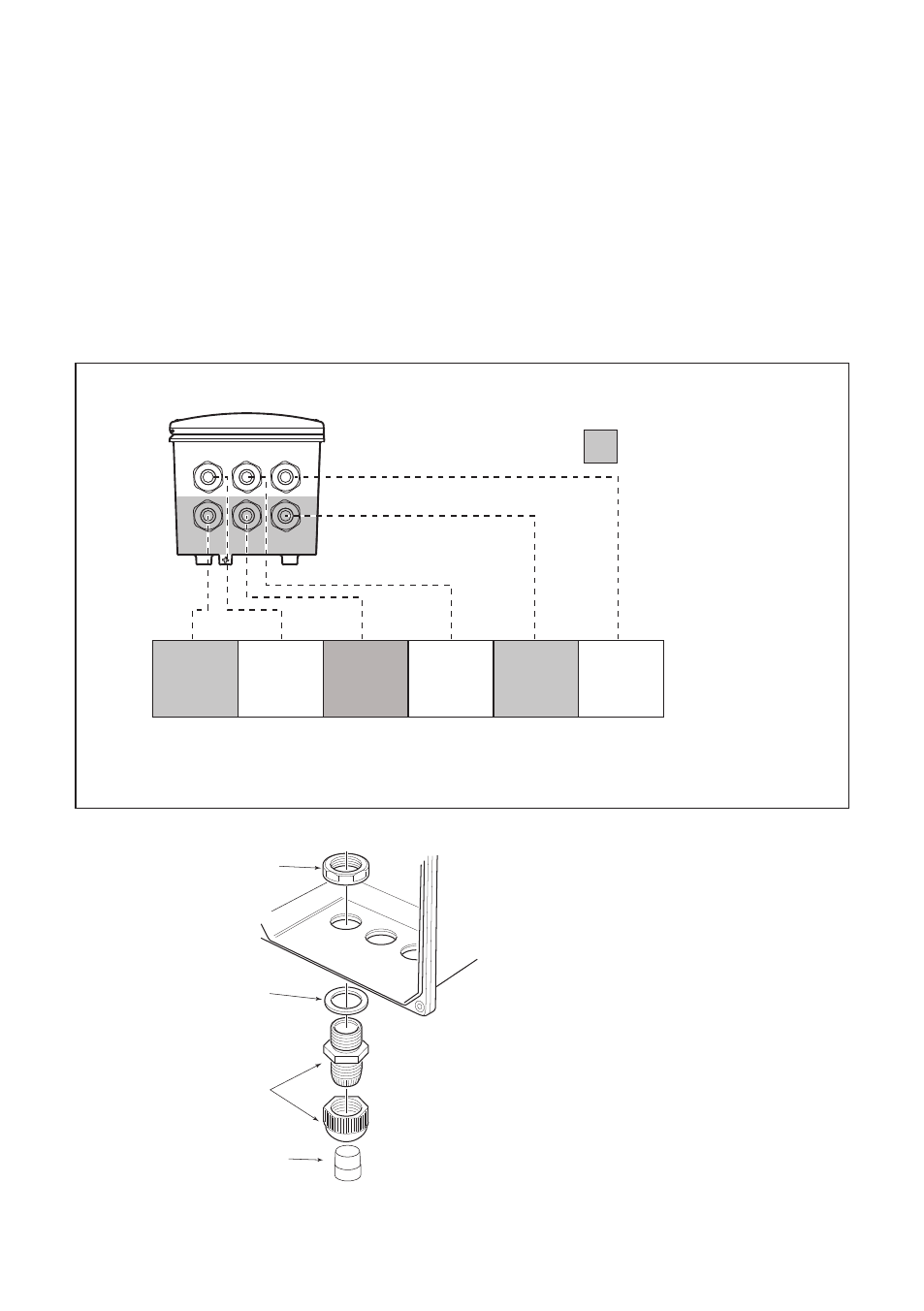
High voltage section
Contact
(S1, S2)
output
cables
mA
cables
Contact
(S3, S4)
output
cables
Sensor
Cables
Input
contact
Power
cable
Suitable for cables with an outside diameter between 6 - 12 mm (0.24 - 0.47”)
Figure 3-5a. Cable glands diagram
3-2-2. Cables, Terminals, glands and conduit
adapter
ISC450G-A(D)-A
The ISC450 is supplied with terminals suitable
for the connection of finished wires in the size
range of 0.13 to 2.5 sq.mm. (26 to 14 AWG).
The cable glands supplied will form a tight seal
on cables with an outside diameter of 6 to 12
mm (0.24 to 0.47 inches). Unused cable entry
holes must be sealed with cable glands includ-
ing the blind plugs supplied.
ISC450G-A(D)-U
The ISC450 is supplied with terminals suitable
for the connection of finished wires in the size
range of 14- 26 AWG. The cable entry holes
are sealed with FM certified plugs. Prior to
cable entry the plugs can be removed with
allen key size 3/8” The cable conduit fittings
can be mounted in the holes of the housing as
required. The cable glands supplied with the
unit will give a tight seal on cables with outside
diameter of 0.24 to 0.47 inches.
Gland nut
O-ring
Gland
Close up plug
Contents:
6 X Gland M20
6 X Close up plug
6 X Gland nut M20
6 X O-ring 17.12 X 2.62 EPDM 70° sh.
NOTE: The glands must be installed properly
to meet IP66 and NEMA 4X rating.
Use close up plug for unused glands.
NOTE: Moisturize O-ring before assembling.
Figure 3-5b. How to install cable glands