6. wiring the sensor, 6-1. general precautions, 6-2. connecting the sensor cable to the converter – Yokogawa ISC450 4-Wire Analyzer for Inductive Conductivity User Manual
Page 20: 6-3. installation of the sensor
12
IM 12D06D05-01E
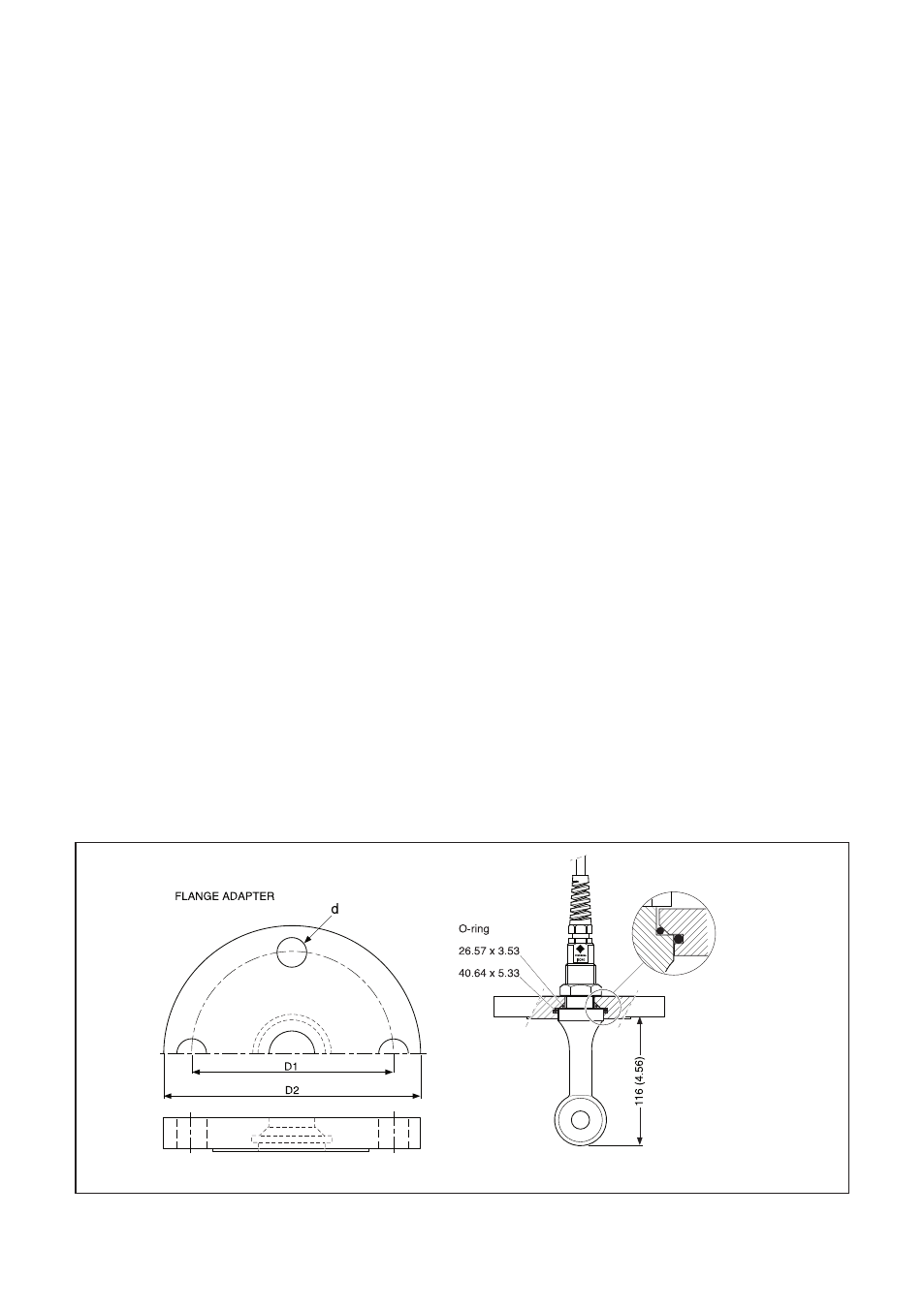
Figure 3-9a. Dimensions
It is necessary to use screening/shielding on
the output signal cables. Terminal 63 is used to
connect the shielding.
3-6. Wiring the sensor
3-6-1. General precautions
The sensor cable transmits low voltage, high
frequency signals and should be installed
separately from any high voltage, high cur rent
and/or power switching cables. This is to avoid
any unintentional cross talk or other kind of
interference of the conductivity meas ure ment.
3-6-2. Connecting the sensor cable to the
converter
1. To access terminals remove the front cov-
er of the EXAxt ISC450G by releasing the
4 captive screws.
2. Loosen the cable gland and pull the ca ble
in the connection compartment.
3. The sensor leads are numbered and the
leads must be connected to the ter mi nals
with the corresponding number, re fer to
Fig. 3-4: the temperature com pen sa tor
with 11/12
- the drive coil with 15/16
- the receive coil with 13/17
Terminal 14 is for connection of the shield.
4. Screw the cable gland tight to en sure IP66
(NEMA 4X) environmental pro tec tion. An
optional protection hose (flexible con duit)
is available for additional me chan i cal pro-
tec tion of the sensor cable.
3-6-3. Installation of the sensor
The Model ISC40 is a “doughnut” shaped sen-
sor. Preferably, the process will flow through
the hole of the donut with the temperature com-
pensator up-stream. For minimal obstruction of
the flow and for accurate measurement without
the need for calibration of the cell constant, the
process will flow freely around the doughnut,
allowing a minimum distance of 25 mm (1”)
between doughnut and process piping (d).
The sensor is provided with a gasket and
retaining nut. This allows “bulkhead mounting”
in tank wall or standard flange through a hole of
27 mm (1.1”) diameter (A). The insertion is 125
mm under the flange.
Two flats are provided with wrench size 20 mm
(0.8”) to allow easy mounting and alignment of
the sensor. The model identification on one flat
aligns with the “up-stream” position of the sen-
sor.For On-line mounting adapters are avail-
able for standard 2” process connection (Gas
thread, NPT, ANSI-flange, DIN-flange).
For by-pass measurement flow fittings are
available in polyporpylene, polyvinylidene flour-
ide and Stainless Steel.
For measurements in open ducts or vessels an
immersion fitting in CPVC or Stainless Steel is
available.
For easy wiring the sensor must be located
within 5 m (15”) from the converter using the
integral sensor cabling.