3. wiring the power supply, 3-1. general precautions, Danger – Yokogawa ISC450 4-Wire Analyzer for Inductive Conductivity User Manual
Page 17
9
IM 12D06D05-01E
3
INSTALLATION
AND
WIRING
3-3. Wiring the power supply
3-3-1. General precautions
Make sure the power supply is switched off.
Also, make sure that the power supply is cor-
rect for the specifications of the EXAxt and that
the supply agrees with the voltage specified on
the textplate.
1. Install an external switch or circuit breaker
to the power supply of the converter.
2. Use an external switch or circuit breaker
rated 5A and conforming to IEC 60947-1
or IEC 60947-3.
3. It is recommended that the external switch
or circuit breaker be installed in the same
room as the converter.
4. The external switch or circuit breaker
should be installed within reach of the
operator and identified with marking as a
power supply switch to the converter.
5. Power lines such as power cables and
contact outputs should be fixed securely
onto a wall or construction using cable
racks, conduit tubing, nylon bands or
other appropriate ways. Accidental
removal from terminals by pulling may
result in electric shock.
Local health and safety regulations may require
an external circuit breaker to be installed. The
instrument is protected internally by a fuse. The
fuse rating is dependent on the supply to the
instrument. The 250 VAC fuses should be of
the “time-lag” type, conforming to IEC127.
DANGER
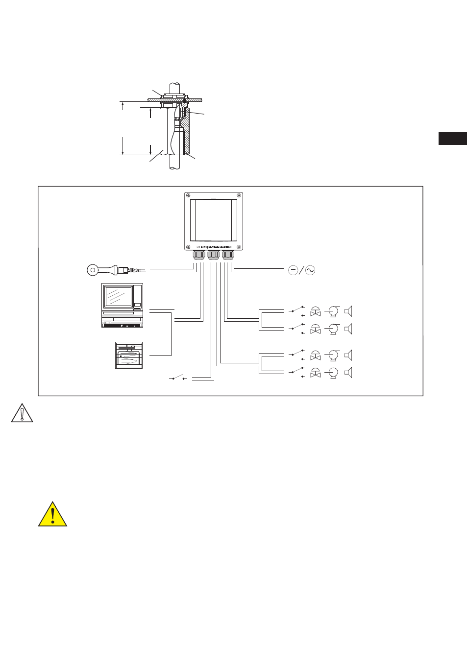
Figure 3-6. System configuration
S1
S2
S4
S3
FRONT GLANDS
REAR GLANDS
Sensor
output
signals
HART
Contact
output
Contact
output
Power
Contact input
mA1
mA2
Adapter for conduit work
When protect the cable with a conduit, replace the M20 cable gland with a cable gland of optional
conduit adapter, and set the adapter shown as Figure 3-5c.
Adapter
49
(1.93
"
)
G1/2 screw (/AFTG), 1/2 NPT screw (/ANSI)
M20 screw (/AM20)
Approx.
55(2.2
"
)
Packing
Unit: mm(inch)
Nut
Figure 3-5c. Conduit adapter