Inspection and maintenance, 1 routine inspection and maintenance, 2 inspection in the event of an error – Yokogawa Low Concentration (ppm) Zirconia Oxygen Analyzer OX400 User Manual
Page 54
<
7. Inspection and Maintenance>
7-1
IM 11M10B01-01E
7. Inspection and Maintenance
Routine inspection and maintenance is important to ensure operation of the OX400 in a good
condition. Perform regular inspection and maintenance in accordance with the following instructions.
7.1 Routine Inspection and Maintenance
1) Checking readings
Measure calibration gas about once every two to three months and check the readings. If an
error is found with the calibration gas concentration, perform zero-span calibration in the range
you use.
2) Checking gas flow rate
Regularly check the sensor gas flow rate in order to make sure that the flow rate is 200 ± 25
ml/min (a floater should be between upper and lower bar of the 200 ml/min bar on flowmeter.)
3) Other
Regularly check for signs of malfunction such as strange noises of the pump and fan, or
unusually high temperature of the case.
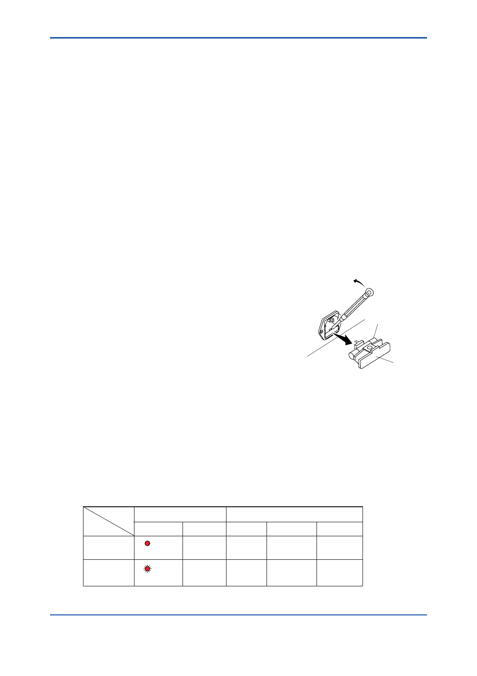
4) Replacing the fuse
Be sure to turn off the power of the OX400 and remove the
power plug from the socket before replacing the fuse. The
fuse is installed in the lower part of the power cord plug on
the rear panel of the OX400 (see right figure). Remove the
power cord from the plug, pull the fuse holder out of the
lower part of the plug, replace the fuse with a new one, and
push the fuse holder back in place. Be sure to replace the
old fuse with a correctly rated one.
If a replaced fuse burns out soon, the circuit is likely to be
defective. Please contact our service department.
7.2 Inspection in the Event of an Error
If an error occurs, the ERR/ALM lamp on the front panel turns on. An error/alarm code is displayed on
the sub-display. If multiple errors occur, codes are displayed in the order of occurrence.
An error means a malfunction, so the heater is turned off and the measurement is stopped. When
an error occurs, repair is required. On the other hand, an alarm means a warning, so measurement
is continued. An alarm occurring during calibration may invalidate the calibration depending on the
content of the alarm.
The following shows the display and output in the event of an error/alarm.
ERR/ALM
ERR/ALM
Error occurs
LED lamp
Alarm occurs
On
Flashing
Sub-display
Err code
ALM code
[ErrX]
[ALMX]
FAIL contact
DO contact
CLOSE
Closed only
in the event
of “ALM7”
OPEN
OPEN
mA output
Scale-out
by burnout
Measurement
output
Front Panel
Rear Panel
Event
Notice
(Note) When burnout function is disabled, the mA output in the event of an error (fail) is “4 mA.”
Furthermore, the mA output during warm-up is also “4 mA.”
FAIL (error) contact and DO (alarm) contact are “OPEN” when the power is OFF.
Fuse Holder
Fuse