Yokogawa Low Concentration (ppm) Zirconia Oxygen Analyzer OX400 User Manual
Page 52
<6. Operation and Parameters>
6-15
IM 11M10B01-01E
6.5 Switching Measurement Flow Path Using
Multi-Selector
This item is an option, so if you did not specify option “/MS,” this function does not work.
When oxygen concentration at multiple locations is measured, the multi-selector allows switching
of measurement flow path using the relay contact output. Three gas flows can be switched from the
panel.
Specify the flow path No. (“1” through “3”) in the maintenance mode “MLS.” The default in “MLS” is “0.”
For details, see Section 6.1.9, “Setting Multi-Selector “MLS”.” Furthermore, output of measurement
flow path data can be performed by combining two contacts.
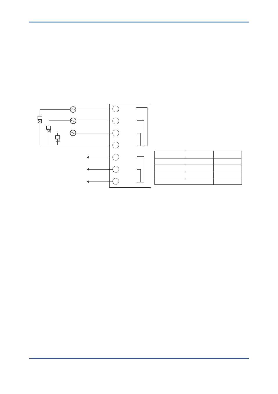
MS1
MS2
MS3
MSI1
MSI2
MSICOM
MSCOM
MSI1-MSICOM MSI2-MSICOM
MS OFF
OPEN
OPEN
MS1 (1st flow)
CLOSE
OPEN
MS2 (2nd flow)
OPEN
CLOSE
MS3 (3rd flow)
CLOSE
CLOSE
Solenoid valve
Contact output for switching of measurement
flow path
1st flow path
2nd flow path
3rd flow path
Power supply
OX400 terminal markings
Contact output to the customer
Output for measurement
flow path data. (Note)
(Note)
The following table shows the relationships of flow
no. contact signals. The flow set in “MLS” closes.
Figure 6.20
Switching Measurement Flow Path Using Multi-Selector
(Example of Three Gas Flows)
When the multi-selector is used, the flow path “MLS1” through “MLS3” under measurement are
displayed on the sub-display on the front panel. If an error or alarm occurs while the multi-selector is
used, the flow path No. and error/alarm are displayed sequentially.