Operation and parameters, Operation and parameters -1 – Yokogawa Low Concentration (ppm) Zirconia Oxygen Analyzer OX400 User Manual
Page 38
<6. Operation and Parameters>
6-1
IM 11M10B01-01E
6. Operation and Parameters
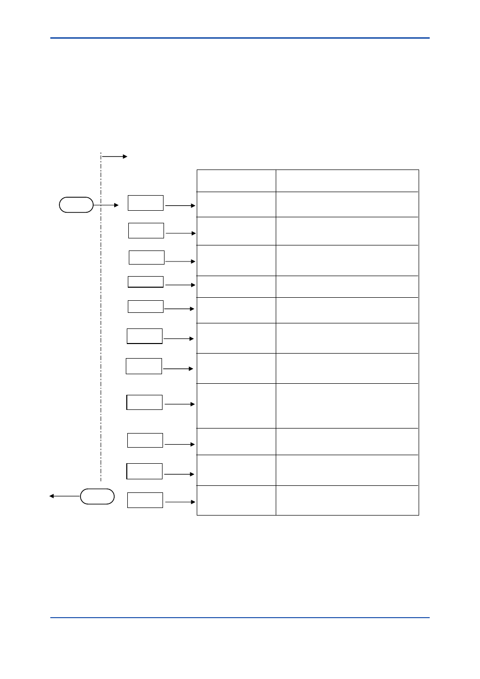
The OX400 has two modes, “Measurement Mode” and “Maintenance Mode.” Oxygen concentration
is displayed in the measurement mode. The setting of operation parameters and calibration operation
are performed in the maintenance mode. Furthermore, the MODE LED on the front panel is on in the
maintenance mode. To enter the maintenance mode, or to return to the measurement mode from the
maintenance mode, hold down the [
MODE] key for two seconds. The parameters shown in Figure 6.1
are available in the maintenance mode. Parameters can be displayed by scrolling with the [▼], [▲]
keys.
MODE
▼↓↑▲
CAL
へ
Hold down
for 2 seconds
Hold down
for 2 seconds
CAL
▼↓↑▲
[ENT]
rnG
oUt2
HoLd
nAMU
ALM
SEt.C
CoEF
rEV
SEnS
▼↓↑▲
▼↓↑▲
▼↓↑▲
▼↓↑▲
▼↓↑▲
▼↓↑▲
▼↓↑▲
▼↓↑▲
▼↓↑▲
MODE
[ENT]
[ENT]
[ENT]
[ENT]
[ENT]
[ENT]
[ENT]
[ENT]
[ENT]
CEL.r
▼↓↑▲
[ENT]
Performs calibration.
(3-point / 2-point / 1-point / Air)
Destination
(reference section)
Maintenance mode
“0-1 V DC”
To “rEV”
To measurement
mode
Description
Default
To Calibration “CAL”
(Section 6.2)
To Displaying Cell
Resistance Value
(Section 6.1.11)
To Setting
Output Range
(Section 6.1.1)
To Setting Secondary
Output (Section 6.1.2)
To Setting Hold
(Section 6.1.3)
To Setting Burnout
(Section 6.1.4)
To Setting Alarms
(Section 6.1.5)
To Setting Calibration
Gas Concentration
(Section 6.1.6)
To Displaying
Calibration Coefficient
(Section 6.1.10)
To Setting Sensor
Constant
(Section 6.1.7)
To Displaying Software
Revision “rEV”
(Section 6.1.12)
For maintenance and diagnosis.
For maintenance and diagnosis.
Sets the
measurement range.
(Auto / Fixed / Partial)
Selects the voltage output.
(0-1 / 0-5 / 0-10 V DC)
Specifies the output hold
during maintenance.
(None/Previous value)
Specifies the burnout function
in the event of a failure
(None / Burn-up / Burn-down)
Sets the oxygen
concentration alarm (DO).
(None / HL&LL / Only HL / Only LL)
Configures the setting at the
time of calibration. (Note 1)
(See 6.2 Calibration “CAL”
when configuring the setting
while performing calibration)
The setting must be configured
when replacing sensors.
(dZ1 / dS1 / dZ4 / dS4 / Con4)
Displays the revision of the
software for maintenance.
“All”
(3-point)
“Auto”
“None”
“None”
“None”
Note 1: When “Air” is selected in Calibration “Cal,” the “SEt.C” menu is not displayed.
Note 2: Some settings are omitted in the above flow chart.
For setting output smoothing function of “SMoo” menu, see Section 6.1.8.
When switching of measurement flow path using the Multi-selector,
set the measurement flow path (1 to 3) in “MLS.” For the operation of the “MLS” menu,
see Section 6.1.9.
Figure 6.1
List of Parameters in Maintenance Mode