3 communication, Communication -5, Caution – Yokogawa Low Concentration (ppm) Zirconia Oxygen Analyzer OX400 User Manual
Page 32
<
4. Piping and Wiring>
4-5
IM 11M10B01-01E
Table 4.3
Measurement Flow Path Switching Output by Multi-selector
MS1-MSCOM
MS2-MSCOM
MS3-MSCOM
MS OFF
0
0
0
MS1 ON (Select flow path 1)
1
0
0
MS2 ON (Select flow path 2)
0
1
0
MS3 ON (Select flow path 3)
0
0
1
• Output of information on flow path under measurement by multi-selector: Answer-back output
of the flow path that is being measured. ”1” when lines between terminals MSI1/MSI2 and
MSICOM are closed, and “0” when open.
Table 4.4
Output of Information on Flow Path under Measurement by Multi-selector
MSI1-MSICOM
MSI2-MSICOM
MS OFF
0
0
MS1 (Flow path 1 under
measurement)
1
0
MS2 (Flow path 2 under
measurement)
0
1
MS3 (Flow path 3 under
measurement)
1
1
CAUTION
Be careful because the contact output is open when the power of the OX400 is OFF.
!
INLET
OUTLET
N200
C
US
R
172608
MS1
RC1
RC2
RC3
DO
FAIL
MS2
MS3
MSI1
MSI2
MSI
COM
SERIAL
(RS232)
FUSE
250V T3.15A
PUMP
OFF
MS
COM
RCCOM
+
+
-
-
mA
V
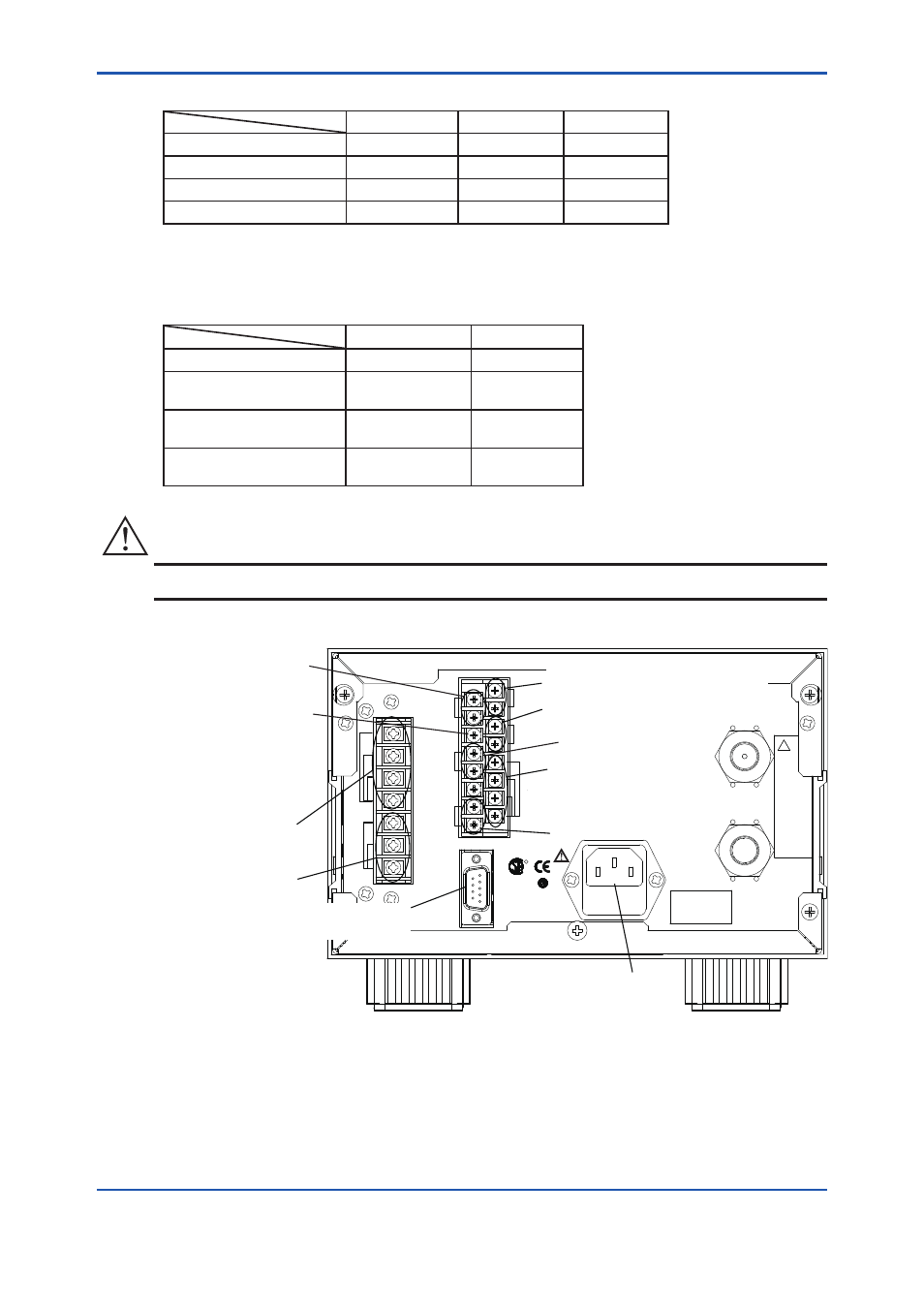
Terminal screws are M3
Primary output terminal
Secondary output terminal
Range marker contact
output terminal
Contact input
(with pump “-P”
option)
G
NOT using
Power cord connector for
two-pole plug with earthing contact
Error (Fail) contact output
terminal
Alarm (DO) contactoutput terminal
(high/low oxygen concentration alarm)
Multi-selector
terminal
(with “/MS” option)
Contact output for
switching of
measurement flow path
Contact output for
measurement flow
path data
RS232 communication
connector
Figure 4.4
Wiring Terminals
4.2.3 Communication
A D-sub 9-pin connector for RS232 communication is located on the rear panel of the OX400. RS232
connection cable length must be no longer than 3 m for CE marking.