2 integral indicator display when powering on, Integral indicator display when powering on -3, Important – Yokogawa EJX930A User Manual
Page 9
<2. Connection>
2-3
IM 01C25R05-01EN
(6) Connecting RS-485 USB Adaptor to EJX
Multivariable Transmitter
For configuration of EJX Multivariable Transmitter
using DTM on PC, RS-485 USB Adaptor is required
to connect transmitter to PC. Connecting RS-485
USB Adaptor to EJX Multivariable Transmitter is
described using BLACK BOX “SP390A-R2” isolated
RS485 USB Adaptor as an example in Figure 2.3
and Figure 2.4.
A
B
+
–
MODBUS
SUPPL
Y
BLACK BOX
TDA(-)
TDB(+)
RDA(-)
RDB(+)
GND
USB
F0206.ai
BLACK BOX
“SP390A-R2” Isolated
RS485 USB Adaptor
EJX Multivariable
Transmitter
RDA(-)
MODBUS A
RDB(+)
MODBUS B
Figure 2.3
RS-485 USB Adaptor connection
RS-485
Echo OFF
2 Wire
2 Wire
RS-422
Echo ON
4 Wire
4 Wire
1
2
3
4
F0207.ai
1 (RS422/RS485)
RS-485
2 (Echo ON/OFF)
Echo OFF
3 (4 Wire/ 2 Wire)
2 Wire
4 (4 Wire/ 2 Wire)
2 Wire
Figure 2.4
RS-485 USB Adaptor Setting
IMPORTANT
Do not connect MODBUS(RS-485) wiring
to Power terminals. It may damage RS-485
adaptor.
NOTE
We recommend isolated RS485 USB Adaptor for
connecting PC to EJX Multivariable Transmitter.
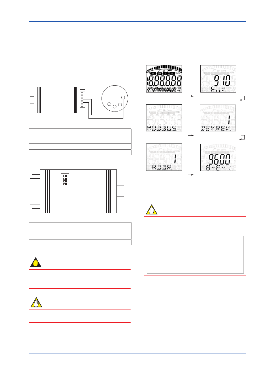
2.2 Integral Indicator Display
When Powering On
For models with the integral indicator code “D”, the
display shows all segments in the LCD and
device/communication information sequentially.
All segments display
Model name (3 s)
Communication Protocol (3 s)
Device Revision (3 s)
Slave Address (3 s)
Serial information (3 s)
F0208.ai
E.g.:
Baud rate: 9600 [bps]
Data Length: 8 [bit]
Parity: Even
Stop Bit: 1
NOTE
LCD display can be set to all segments display
only.
• Procedure to call up the display
[Root Menu] → Detailed setup → Display condition
→ Chg power on info
On
Show all segments display and
device/communication information
display when powering on.
Off
Show all segments display when
powering on.