Diagnostics, 1 self-diagnostics, 2 checking with integral indicator – Yokogawa EJX930A User Manual
Page 26: 3 status information, Diagnostics -1, Self-diagnostics -1 4.1.1, Checking with integral indicator -1, Status information -1
<4. Diagnostics>
4-1
IM 01C25R05-01EN
4. Diagnostics
4.1 Self-Diagnostics
4.1.1 Identify Problems by Using the
Configuration Tool
The configuration tool can be used to run self-
diagnostics on a transmitter and check for incorrect
data settings.
The
Status menu is available for self-diagnostics.
If the specific diagnostic item is known for the
check, you can directly call up the item by using the
Status menu.
The status is categorized from 1 to 11.
See Table 4.1 to determine the status group.
Show an example below to confirm the status of
Status group 1.
• Procedure to call up the Status display
[Root Menu] → Diag/Service → Status → Status group 1
If no error is detected, check mark is cleared on the
configuration tool.
If there is an error, “check mark” is displayed on the
configuration tool, and a countermeasure for that
error is necessary.
In addition to
Status group 1-11 parameters,
Status Bytes parameter in Address Map (Basic
Information) is available.
[Root Menu] →Diag/Service → Status
→ Status Bytes
Status information only mapped in
Address Map (Basic Information)
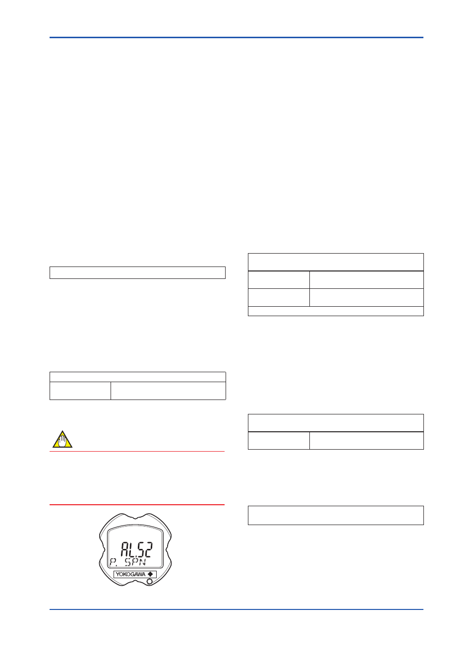
4.1.2 Checking with Integral Indicator
NOTE
If an error is detected by running self-diagnostics,
an error number is displayed on the integral
indicator. If there is more than one error, the error
number changes at three-second intervals.
See Table 4.1 regarding the alarm codes.
F0401.ai
Figure 4.1
Integral Indicator
4.1.3 Status Information
(1) Data quality and Limit status
EJX multivariable transmitter can handle
Device Variables (DP(Pres), SP, ET. Each
variable contains data quality and limit status
for providing useful status about the data value.
The data quality is normally “Good”. However,
in the case of a sensor failure or out of
measurement range, it turns to “Bad” or “Poor
Accuracy”. The limit status indicates whether
the data value is limited (i.e., not responding
to the process). When the limit status is
“Constant”, the value will not be changed. For
detail, refer to Table 4.1 and 4.2.
• Procedure to call up the display
[Device Variables]
[Root Menu] → Process variables → Device variables
and Status →
→ Press Data
Quality
Good, Poor Accuracy, Manual/
Fixed, or Bad is displayed.
→ press Limit
Status
Constant, Low Limit, High Limit, or
Not Limited is displayed.
It is the same about the SP and ET.
(2) Configuration Change Counter
The Configuration Change Counter is
incremented once for every user action
that changes the device’s configuration or
calibration. This value is never reset or written
and maintained even if power is removed from
the device.
• Procedure to call up the display
[Root Menu] → Diag/Service → Status →
→ Cfg chng
count
The configuration change times
are counted.
(3) Reset Configuration Change Counter
Configuration Change Counter can be reset by
this method.
• Procedure to call up the display
[Root Menu] → Diag/Service → Status → Reset Cfg
Chng Count