Yokogawa EJX930A User Manual
Page 25
<3. Parameter Setting>
3-15
IM 01C25R05-01EN
(2) Device Variable Simulation Function
Using the simulation function, the output signal can
be confirmed by setting any value and status to the
selected device variable.
Call up the parameter and follow the message
shown.
After completing the step 5, the simulation starts.
Integral indicator shows output and alarm (AL.91)
alternately.
• Procedure of device variable simulation
Step 1 Call up the
parameter
[Root Menu] → Diag/
Service → Test → Simulate
2
Selection of
Device Variable
Select one parameter from
the list below
Off
Pres
SP
ET
3
Setting of Value
Input the simulate value
4
Setting of Data
quality
Select one parameter from
the list below
Bad
Poor accuracy
Manual / Fixed
Good
5
Setting of Limit
status
Select one parameter from
the list below
Not limited
Low limited
High limited
Constant
NOTE
• All the simulations for differential pressure,
static pressure and external temperature,
are reflected to the output. Accordingly,
LCD display, and communication output are
directly corresponded to the simulate value.
The alarm output is also available according
to the simulate value.
• Damping is applicable for differential
pressure, static pressure, and external
temperature simulation.
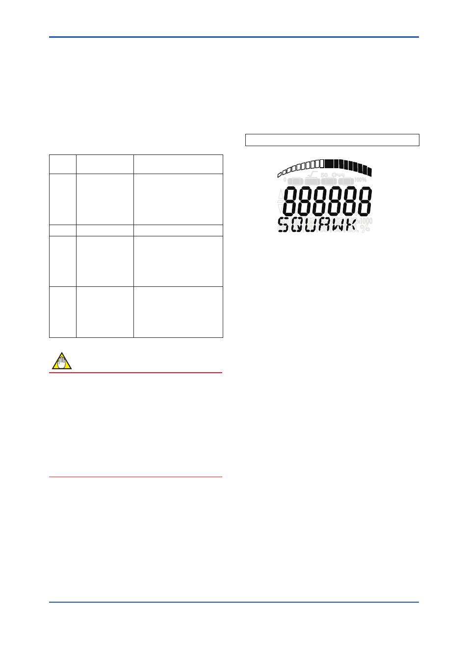
(3) Squawk
This feature can be used to identify the
communicating transmitter by remotely causing
LCD to display the particular pattern as shown in
the Figure 3.3.
“SQUAWK” continues for approximately 10
seconds, then is released automatically.
• Procedure to call up the
Squawk display
[Root Menu] → Diag/Service → Test → Squawk
P
SP
T
F
F0307.ai
Figure 3.3
LCD display for Squawk