Connection, 1 connection with the modbus host, 1 the hardware switch – Yokogawa EJX930A User Manual
Page 7: Connection -1, Connection with the modbus host -1 2.1.1, The hardware switch -1
<2. Connection>
2-1
IM 01C25R05-01EN
2. Connection
2.1 Connection with the Modbus
Host
2.1.1 The Hardware Switch
The Hardware switch is located in the CPU Board
Assembly. In order to accessing the switch,
removing the LCD Board is required. Refer to
IM 01C25R01-01E “EJX910A and EJX930A
Multivariable Transmitters” Chapter 9 for detail
instruction.
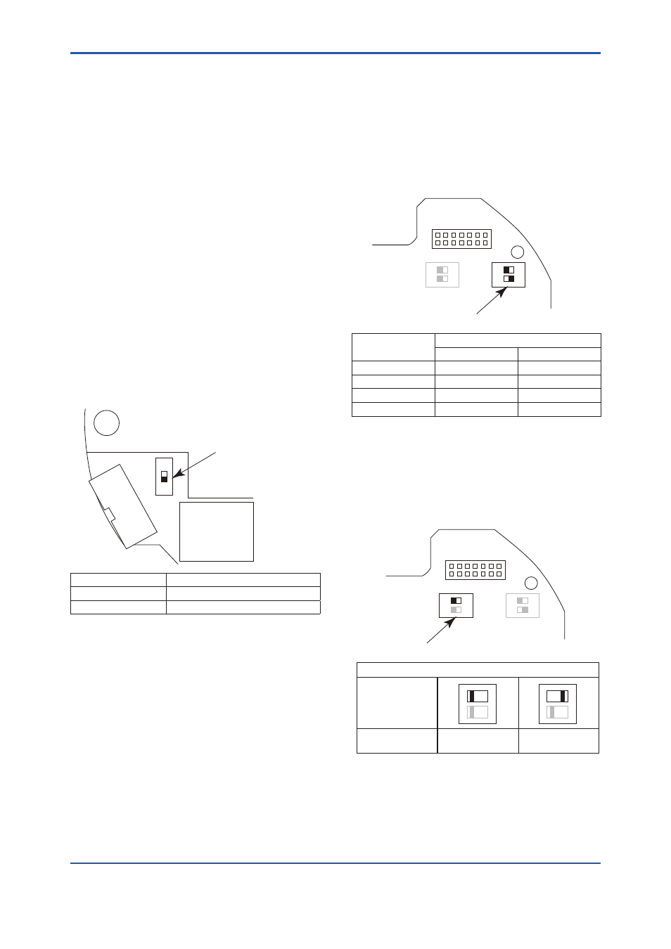
(1) Termination
The RS-485 bus requires Line Termination near
each of the 2 Ends of the Bus, and not allowed to
place more than 2. By using hardware switch, “the
bus end” is settable. This switch decides “the bus
end” or “the not bus end” on the RS-485 line. If the
hardware switch is ON, “the bus end” is selected. If
it is OFF, the mode is “the not bus end”.
CN1
SW2
OFF
ON
Terminator Switch
F0201.ai
Terminator Mode
Position of “ON” and “OFF”
Bus End
ON: Upper side
Not Bus End *
OFF: Lower side
*:
Factory default setting.
(2) Baud Rate
By using hardware switch, the baud rate is settable.
The combinations of ON and OFF corresponds to
each baud rate. After turning on the power supply,
the selected baud rate is activated.
1
2
N
O
1
2
N
O
SW2
BAUD
RATE
GND
SW1
WP
CN1
Baud Rate Switch
F0202.ai
Baud rate [bps] Combinations of “ON” and “OFF”
1 (Upper side)
2 (Lower Side)
1200
OFF
OFF
4800
ON
OFF
9600*
OFF
ON
19200
ON
ON
*:
Factory default setting.
(3) Write Protect Hardware Switch
There is a slide switch on the CPU assembly board.
Write protection function is activated which disables
all the write possible parameters change through
communication.
1
2
N
O
1
2
N
O
SW2
BAUD
RATE
GND
SW1
WP
CN1
Write Protection Switch
F0203.ai
Write Protection
Switch (1) Position
1
2
O
N
1
2
O
N
Hardware write protection switch (WP)
Write Protection
YES
(Write disabled)
NO*
(Write enabled)
*:
Factory default setting.