How to connect the dc power cord – Proface GP4600R - 12.1 Standard HMIs with Rear Mounting Options" User Manual
Page 28
29
Wiring
En
g
lish
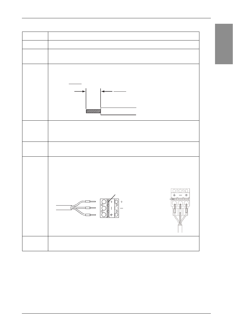
How to connect the DC Power Cord
Note:
•
Do not solder the wire directly to the power receptacle pin.
•
To prevent the possibility of a terminal short, use a pin terminal that has an insulating
sleeve.
•
The DC power supply connector for GP-4200/4300/4400 Series can be connected to
GP-4500/4600 Series. However, the DC power supply connector for GP-4500/4600
Series is unable to connect to GP-4200/4300/4400 Series.
Step
Action
1
Confirm the power cord is not connected to the power supply.
2
Check the rated voltage, and remove the “DC24V” sticker on
the DC power supply connector.
3
Remove 10 mm (0.39 in.) of the vinyl membrane off the ends
of the power cord wires.
4
If using stranded wire, twist the ends. Tinning the ends with
solder reduces risk of fraying and ensures good electrical
transfer.
5
Push the Opening button with a small and flat screwdriver to
open the desired pin hole.
6
Insert each pin terminal into its corresponding holder. Release
the Opening button to clamp the pin in place.
7
After inserting all three pins, insert the DC power supply
connector into the power connector on the GP unit.
mm
in.
10
0.39
DC Power Cord
Opening Button
FG
(24V)
(0V)
GP-4200 Series / GP-4300 Series /
GP-4400 Series
GP-4500 Series /
GP-4600 Series
Opening Button
FG
+
-
- GP4500R - 10.4 Standard HMIs with Rear Mounting Options" GP4400R - 7.5 Standard HMI with Rear Mounting Options" GP4300R - 5.7 Standard HMI with Rear Mount" GP4300M - 5.7 Modular HMI" GP4200M - 3.5 Modular HMI" GP4500 - 10.4 W Model HMI" GP4400 - 7.0 W Model HMI" GP4300 - 5.7 W Model HMI" GP4200 - 3.5 W Model HMI" GP4600 - 12.1 Standard HMIs" GP4500 - 10.4 Standard HMIs" GP4400 - 7.5 Standard HMI" GP4300 - 5.7 Standard HMI" GP4200 - 3.5 Standard HMIs"