Series 35 serpar, Double valves with e-p monitor, Overview of valve function – Ross Controls SERPAR AND CROSSFLOW DOUBLE VALVES SERIES 35 User Manual
Page 9
www.rosscontrols.com
9
STANDARD SPECIFICATIONS: For valves on this page.
Pilot Solenoids: Two, rated for continuous duty.
Standard voltages: 100-110 volts, 50 Hz; 100-120 volts, 60 Hz;
24 volts DC; 110 volts DC. Other voltages available.
Power Consumption: Each solenoid, 87 VA inrush, 30 VA holding
on 50 or 60 Hz; 14 watts on DC.
E-P Reset Solenoid: Rated for intermittent duty.
Voltages: 24-48 or 100-120 volts AC or DC (for E-P only).
Ambient Temperature: 40° to 120°F (4° to 50°C).
Media Temperature: 40° to 175°F (4° to 80°C).
Flow Media: Filtered air; 5 micron recommended.
Pressure Range: 30 to 125 psig (2 to 8.5 bar).
IMPORTANT NOTE: Please read carefully and thoroughly all of the CAUTIONS on the inside back cover.
Series 35 SERPAR
®
Double Valves with
E-P
Monitor
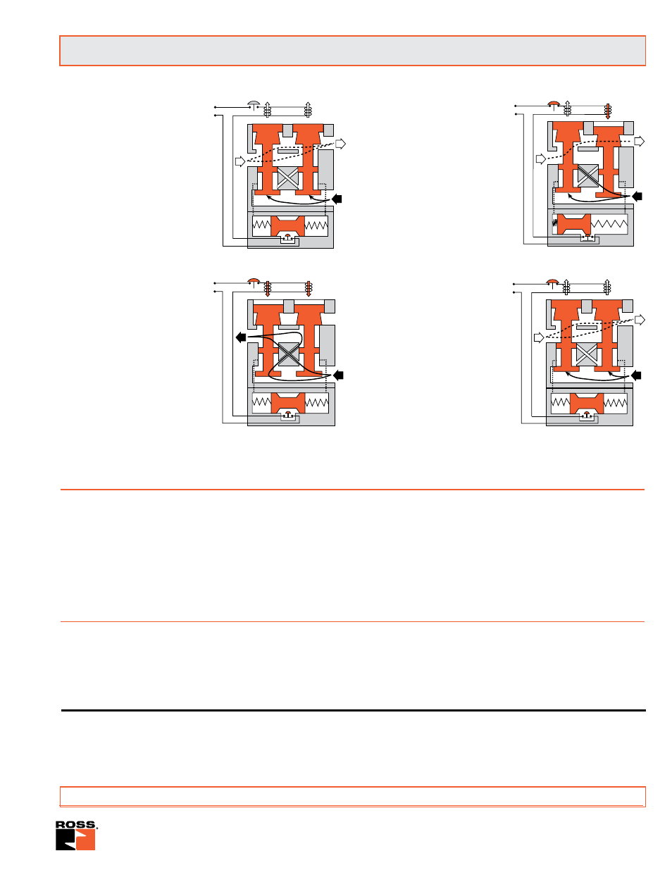
Conditions at start:
Inlet 1 is closed to outlet 2 by both
valve elements A and B. Outlet 2
is open to exhaust 3. Contacts of
switch SW are closed. Monitoring
pressure signals at both ends of
spool S are exhausted.
Normal operation:
Simultaneously energizing both
solenoids actuates both pilots and
causes valve elements A and B
to shift. Inlet 1 is then connected
to outlet 2 via crossflow passages
C and D. Exhaust 3 is closed.
Monitoring pressure signals go to
each end of spool S and become
equal to inlet pressure.
Completition of normal cycle:
Simultaneously deenergizing
both solenoids returns the valve
to the “Conditions at Star t”
described at left.
Detecting a malfunction:
A malfunction in the system or the
valve itself could cause one valve
element to be open and the other
closed. Air then flows past the inlet
poppet on valve element A, into
crossflow passage D, but is substantially blocked by the spool
portion of element B. The large size of the open exhaust passage
past element B keeps the pressure
at the outlet port below two percent
of inlet pressure. Full monitoring air
pressure from side A goes to the
right end of spool S, and a reduced
pressure goes to the left end. This
pressure imbalance causes the
spool to shift to the left. This trips
switch SW, breaks the electrical
circuit to the pilot solenoids, and
allows valve element A to return to
the closed position.
E-P monitor locked-out:
With both valve elements
closed, monitoring air pressure
is exhausted from both ends of
spool S so that it returns to its
normal position. The electrical
circuit to the pilot solenoids
remains broken by switch SW.
To restore the electrical circuit
and return the valve to normal
operation, the reset solenoid
(not shown) must be briefly
energized to reset switch SW.
During and following reset,
the pilot solenoids must be
kept deenergized to prevent
inadvertent and possibly dangerous
cycling of the press. Prolonged energizing of the reset solenoid
can cause burnout and nullify the reset function.
A
B
1
3
2
C D
Pb
Pa
SW
S
A
B
1
3
2
Pb
Pa
SW
S
Conditions at start:
A
B
1
3
2
C D
Pb
Pa
SW
S
Normal operation:
Detecting a malfunction:
A
B
1
3
2
Pb
Pa
SW
S
E-P monitor locked-out:
CAUTION ON THE USE OF RESET SOLENOID
The reset solenoid is rated only for intermittent duty.
Energizing it continuously will lead to solenoid burnout and nullify the reset function.
Overview of Valve Function
For accessories please see page 17.
Single Input Signal and Dual Input Signal models are available in the E-P series of double valves. Both models can be
equipped with, or without, manual overrides.
Single input valves require only one main solenoid signal wired into the terminal strip of the E-P monitored double valve. The
main solenoid signal is wired into terminal 1 and internally jumpered to the second main solenoid. Commons are wired into
terminal 3. This allows both solenoids to be energized and de-energized simultaneously for proper valve operation.
Dual Input valves require two solenoid signals wired independently into the terminal strip of the E-P monitored double valve.
One main solenoid signal is wired into terminal 1 and the second main solenoid signal is wired into terminal 5. Commons are
wired into terminal 3. Both solenoid signals must arrive simultaneously for proper valve operation.