Overview of serpar and crossflow function, Serpar, And crossflow – Ross Controls SERPAR AND CROSSFLOW DOUBLE VALVES SERIES 35 User Manual
Page 4: Double valves, Overview of serpar, Functions
4
ROSS CONTROLS
®
SERPAR
®
and Crossflow
TM
Double Valves
The design of the SERPAR
®
and Crossflow
TM
double valve is distinguished by
crossflow passages and spool valving on the main valve stems. This arrangement
provides the valve’s unique flow characteristics.
Monitors: Self-contained monitors, designed to inhibit valve operation in case of
a fault within the valve, are built into the valve assembly. There are three types of
ROSS monitors available: pneumatic, electro-pneumatic, and electronic.
Valve Sizes: ROSS double valves are available in four sizes. For convenience, valves
are designated by the nominal sizes 4, 8, 12, and 30. These sizes approximate
an average of the flow coefficients (C
V
) of the various flow paths through the valve.
Further information about C
V
ratings is given on page 14.
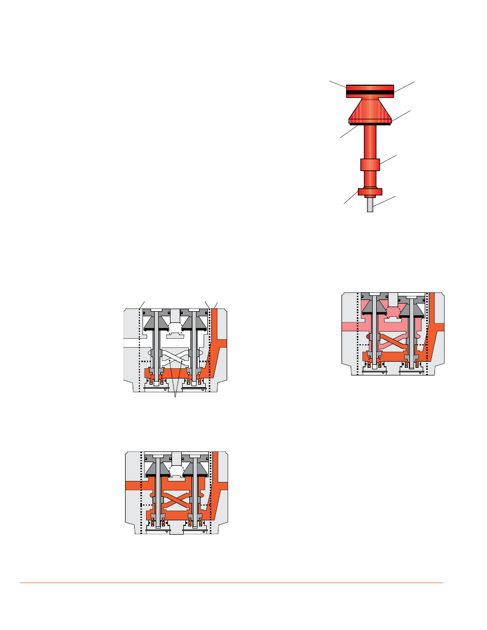
Valve Element Construction: The dual valve elements are of lightweight
construction. Their low inertia allows them to respond quickly to actuating and
deactuating forces. Impact loads are also kept small to help assure long valve life.
Each valve element is guided at the top by the piston and at the bottom by the
stainless steel stem, and there is no sliding bearing surface between.
Buna N Lip Seal
Delrin Piston
Buna N
Poppet Seal
Delrin Poppet
Support
Delrin Spool
Polyurethane
Inlet Poppet
Stainless Steel
Stem
Air flow paths:
Parallel flow paths develop
equal forces on the valve
elements in both the actuated
and deactuated modes. This
enables both valve elements
to respond equally to pilot
pressures and promotes
synchronous movement of
the valve elements. The air
flow paths for the valve in
different operating modes are
shown below.
Valve elements
de-actuated:
With both inlet poppets
closed, inlet air pressure
holds each poppet firmly
against its seat. Exhaust
poppets are open to an
oversized exhaust por t,
and monitoring air pressure
signals are zero. Monitoring
air passages (shown as
dashed lines) go upward or
downward depending on the
location of the monitoring
device being used.
Valve elements actuated:
With the valve elements
in the actuated position,
inlet air is free to flow past
the two inlet poppets and
through the two crossflow
passages to the outlet port.
The exhaust poppets close
off the exhaust port, and
monitoring pressure signals
become equal to inlet pressure.
When the valve is returned to the deactuated position (see figure
at top of this page), the design of the spool elements (on the valve
stem) allows any pressure remaining in the monitoring or crossflow
passages to be exhausted through the open exhaust port.
Detecting a malfunction:
A malfunction in the system or in the valve itself could cause one
valve element to be open and the other closed. In this event inlet
air from the open inlet poppet is substantially blocked from the
outlet port by the spool on the closed valve element. The large
size of the open exhaust passage serves to keep the pressure
at the outlet port below two percent of the inlet pressure.
The monitoring pressure signal from the open valve element is
equal to inlet pressure, while the monitoring signal from the closed
valve element is very small. The monitor senses the difference
between these two pressures and uses this information to shut
down the valve and inhibit further valve action. After the cause
of the malfunction has been corrected and the electrical signal
has been removed from the pilot solenoid, the monitor can be
reset and normal operation can be resumed.
OUT
IN
EXH
Crossflow Passages
Monitoring Air Passages
Pilot Air
Passage
OUT
IN
EXH
OUT
IN
EXH
Overview of SERPAR
®
and Crossflow
TM
Functions