Series 35 serpar, Double valves with l-g monitor – Ross Controls SERPAR AND CROSSFLOW DOUBLE VALVES SERIES 35 User Manual
Page 6
6
ROSS CONTROLS
®
STANDARD SPECIFICATIONS: For valves with L-G monitor.
Pilot Solenoids: Two, rated for continuous duty.
Standard voltages: 100-110 volts, 50 Hz; 100-120 volts, 60 Hz;
24 volts DC; 110 volts DC. For other voltages, consult ROSS.
Power Consumption:
Size 4: Each solenoid, 30 VA inrush, 16 VA holding on 50 or 60 Hz;
11 watts on DC.
Sizes 8,12,30: Each solenoid, 87 VA inrush, 30 VA holding on 50
or 60 Hz; 14 watts on DC.
Electrical Connections: Size 4 uses cord-grip connectors at
solenoids. Order connectors separately on Serpar
®
size 4; terminal
strip on sizes 8, 12 and 30.
Ambient Temperature: 40° to 120°F (4° to 50°C).
Media Temperature: 40° to 175°F (4° to 80°C).
Flow Media: Filtered air; 5 micron recommended.
Inlet Pressure: Size 4: 30 to 100 psig (2 to 7 bar).
Sizes 8,12,30: 30 to 125 psig (2 to 8.5 bar).
L-G Reset Pressure: Size 4: Remote pneumatic reset models
require a pressure of at least 30 psig (2 bar). Manual reset models
use internal valve pressure.
Sizes 8,12,30: 60 psig (4 bar) minimum.
Inlet Port: Models are available with the inlet port on either the right
or the left side of the valve body (size 4 only).
IMPORTANT NOTE: Please read carefully and thoroughly all of the CAUTIONS on the inside back cover.
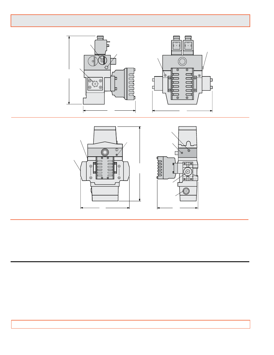
A
C
(4 places)
B
Port 2
(outlet)
1/8 pneumatic
reset port
Port
1
(inlet
)
1/2 NPSC
electrical
opening
1/8 Lockout
indicator
1/8 external
pilot supply
port
Right
Side
Left
Side
Inlet or
outlet
port
C
1/8 Remote
pneumatic
reset port or
manual reset
7.8 (0.31)
2 places
10-32 Lockout
Indicator Port
1/8” Lockout
Indicator Port
B
A
Size 4
Size 8, 12, 30
NOTE: For external pilot models consult ROSS.
Series 35 SERPAR
®
Double Valves with
L-G
Monitor
VALVE OPERATION
Both solenoids must be energized simultaneously to shift the
valve; maintained signal required to keep valve shifted.
WARNING: If monitor must be reset, electrical signals to both
solenoids must be removed to prevent the machine controlled
by the valve from immediately recycling and producing a
potentially hazardous condition.
OPTIONS
Valve Without Piping Flanges: See above.
Valve Without Silencer: Exhaust port has threaded flange only.
Consult ROSS.
Valve Response Time (msec) = M + F • V
See page 18 for response time values.