Series 35 crossflow, Double valves with pressure switches, Overview of valve function – Ross Controls SERPAR AND CROSSFLOW DOUBLE VALVES SERIES 35 User Manual
Page 16: Ab 1 3 2
16
ROSS CONTROLS
®
Series 35 Crossflow
TM
Double Valves with
Pressure Switches*
A
B
1
3
2
Pb
Pa
SWB
1
4
2
SWA
1
4
2
*NOTE: These models have two pressure switches that sense pressure in the sensing ports resulting from the movement of
corresponding valve elements. The pressure switches only indicate if the valve elements do not move in unison.
The switches will not lock out the valve without the addition of an external monitoring system and should not be confused with a
monitor. If lock-out capability is advisable for your application, be sure to connect the pressure switches to an external monitor.
If an internal monitor is preferred, use a model with LG, EP, or DS monitor.
These models are also available with:
1) no pressure switches installed, but with provision for installing pressure switches later, or
2) with no switches installed and no provision for installing them later.
The models with no provision for pressure switches are not capable of being monitored and should not be used in applications
where lock-out capability is a requirement, i.e. press clutch/brakes.
SWITCH OPERATION: Each pressure switch has four electrical contacts. Contacts 1 and 2 are connected when no air pressure
signal is applied to the switch. Contacts 1 and 4 are connected when an air pressure signal is applied to the switch. Contact 3
is for a ground connection.
For further information in the use or connection of the pressure switches call your local ROSS distributor or, in the U.S.A., call ROSS Technical
Services at 1-888-TEK-ROSS.
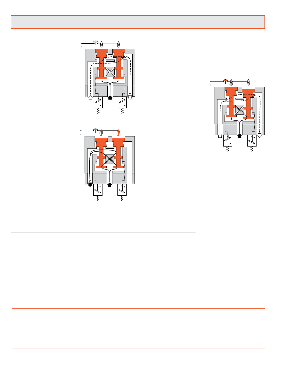
Conditions at start:
Inlet 1 is closed to outlet 2 by both
valve elements A and B. Outlet
2 is open to exhaust 3. Pressure
signals at both switches SWA and
SWB are exhausted. Contacts 1
and 2 of switches SWA and SWB
are connected.
Normal operation:
Simultaneously energizing both
solenoids actuates both pilots and
causes valve elements A and B
to shift. Inlet 1 is then connected
to outlet 2 via crossflow passages
C and D. Exhaust 3 is closed.
Sensing pressure signals go to
each pressure switch and become
equal to inlet pressure. Both
switches trip and now contacts 1
and 4 of switches SWA and SWB
are connected instead of contacts
1 and 2.
Completition of normal cycle:
Simultaneously de-energizing
both solenoids returns the valve
and switches to the “Conditions
at Start” described above.
Detecting a malfunction:
A malfunction in the system or
the valve itself could cause one
valve element to be open and the
other closed. Air then flows past
the inlet poppet on valve element
A, into crossflow passage D, but
is substantially blocked by the
spool portion of element B. The
large size of the open exhaust
passage past element B keeps
the pressure at the outlet port
below 2 % of inlet pressure. Full
sensing air pressure from side
A goes to switch SWA, and a
reduced pressure goes to switch
SWB. This full pressure signal
causes switch SWA to trip. Switch
SWB, with a reduced pressure
signal, does not trip. An external
monitoring system can detect
the malfunction by monitoring
the condition of the switches
SWA and SWB. The external
monitoring system may then react
accordingly by shutting down the
power to the valve solenoids and
any other components deemed
necessary to stop the machine.
See note below.
A
B
1
3
2
Pb
Pa
2
SWA
1
4
2
SWB
1
4
C D
A
B
1
3
2
Pb
Pa
2
C D
SWB
1
4
SWA
1
4
2
Conditions at start:
Normal operation:
Detecting a malfunction:
Double Valves with Pressure Switches for External Monitoring feature:
Designed to enable users to comply with current safety regulations
•
Can be integrated with external monitoring systems to provide for lockout and inhibiting further machine operation until the
•
controls system is reset
Default to de-energized position upon fault condition
•
Built-in non-clogging silencers on Sizes 4, 8, 12 and 30.
•
Overview of Valve Function