Series 35 serpar, Double valves with d-s monitor, Overview of valve function – Ross Controls SERPAR AND CROSSFLOW DOUBLE VALVES SERIES 35 User Manual
Page 11
www.rosscontrols.com
11
STANDARD SPECIFICATIONS: For valves on this page.
Pilot Solenoids: Two, rated for continuous duty.
Standard voltages: 100-110 volts, 50 Hz; 100-120 volts, 60 Hz;
24 volts DC; 110 volts DC. Uses same voltage and frequency
as pilot solenoids, but power supply must be independent and
continuous.
Power Consumption: Each solenoid, 87 VA inrush, 30 VA holding
on 50 or 60 Hz; 14 watts on DC.
Ambient Temperature: 40° to 120°F (4° to 50°C).
Media Temperature: 40° to 175°F (4° to 80°C).
Flow Media: Filtered air; 5 micron recommended.
Pressure Range: 30 to 125 psig (2 to 8.5 bar).
IMPORTANT NOTE: Please read carefully and thoroughly all of the CAUTIONS on the inside back cover.
A
B
1
3
2
C D
Ib Ia
COMPARATOR
and CONTROL
CIRCUITS
SWb
SWa
Sb
Sa
Pb
Pa
A
B
1
3
2
Pb
Pa
Ib Ia
COMPARATOR
and CONTROL
CIRCUITS
SWb
SWa
Sb
Sa
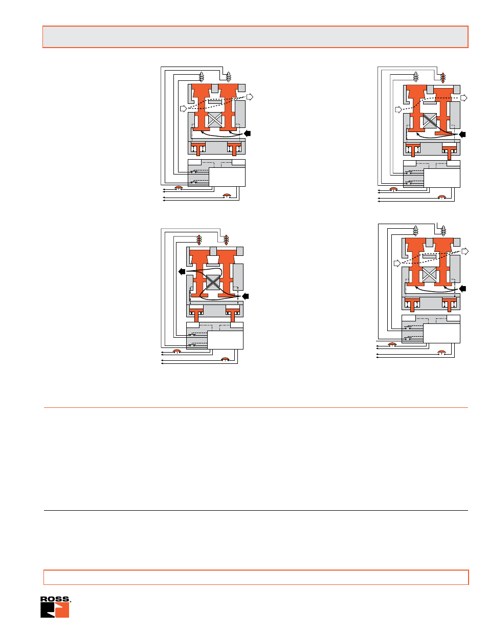
Conditions at start:
Inlet 1 is closed to outlet 2 by both
valve elements A and B. Outlet 2
is open to exhaust 3. Contacts of
switch SW are closed. Monitoring
pressure signals at both ends of
spool S are exhausted.
Normal operation:
Simultaneously energizing both
solenoids actuates both pilots and
causes valve elements A and B to
shift. Inlet 1 is then connected to
outlet 2 via crossflow passages
C and D. Exhaust 3 is closed.
Monitoring pressure signals go
to pressure indicators Ia and
Ib, causing the indicator pins
to be extended and to actuate
proximity switches SWa and
SWb. In normal operation, each
pair - solenoids, valve elements,
indicators, and proximity switches
- responds in unison so that the
comparator circuits “read” the
operation as normal.
Completition of normal cycle:
Simultaneously deenergizing both
solenoids returns the valve to the
“Conditions at Start” described
at left.
Detecting a malfunction:
A malfunction in the system or the
valve itself could cause one valve
element to be open and the other
closed. Air then flows past the
inlet poppet on valve element A,
into crossflow passage D, but is
substantially blocked by the spool
portion of element B. The large
size of the open exhaust passage
past element B keeps the pressure
at the outlet port below two percent
of inlet pressure. Full monitoring
air pressure from side A goes
to pressure indicator Ia so that
its pin is extended and actuates
proximity switch SWa. When
the time interval between the
signal to a solenoid and the signal
from its corresponding proximity
switch exceeds approximately
175 milliseconds, the D-S monitor
breaks contacts Sa and Sb as soon
as solenoid power is removed. This
allows valve element A to return to
the closed position.
D-S monitor locked-out:
With the valve locked out by
contacts Sa and Sb, solenoids
Pa and Pb cannot be energized.
The monitor must be reset before
another valve cycle can begin.
Reset can be achieved by a
separately connected ancillary
switch, but not if the pilot solenoids
are energized. The monitor can be
reset by removing and reapplying
power to the monitor even when the
pilot solenoids are energized. For
this reason it is necessary to have
the pilot solenoids deenergized
during and following reset to
prevent inadvertent and possibly
dangerous cycling of the press.
A
B
1
3
2
Pb
Pa
Ib Ia
COMPARATOR
and CONTROL
CIRCUITS
SWb
SWa
Sb
Sa
A
B
1
3
2
C D
Ib Ia
COMPARATOR
and CONTROL
CIRCUITS
SWb
SWa
Sb
Sa
Pb
Pa
Series 35 SERPAR
®
Double Valves with
D-S
Monitor
Conditions at start:
Normal operation:
Detecting a malfunction:
D-S monitor locked-out:
Overview of Valve Function
For accessories please see page 17.
D-S Monitor Double Valves include a self-contained, dynamic, electronic monitor that checks for proper valve operation
during each cycle. Allowable discordance between each internal element is fixed at 175ms and is non-adjustable. A separate
monitor power supply is wired into the terminal strip and must be constant, i.e. non-interruptible. Valve monitor faults, when
detected, are not revealed until the valve cycle is complete, e.g. the valve is de-energized, allowing for completion of the
current press stroke. Monitor reset must include a
dry contact
wired into terminals G and H to properly reset the valve.
Applying power to the reset terminals will result in monitor damage.