Serpar crossflow double valves with e-p monitor, Series 35 serpar, Double valves with e-p monitor – Ross Controls SERPAR AND CROSSFLOW DOUBLE VALVES SERIES 35 User Manual
Page 8
8
ROSS CONTROLS
®
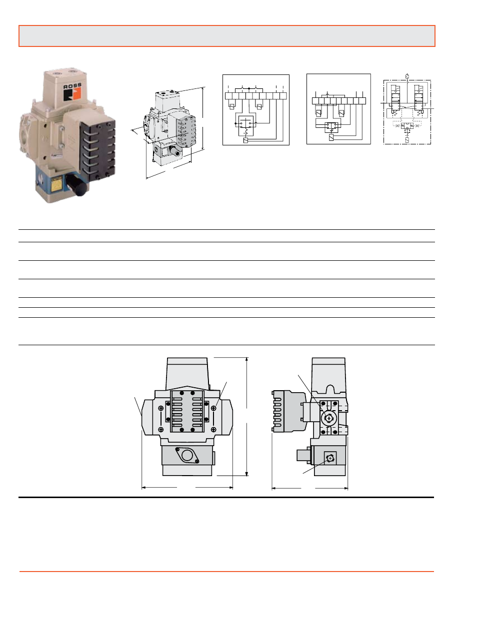
Series 35 SERPAR
®
Double Valves with
E-P
Monitor
A
C
(4 places)
B
Port 2
(outlet)
Port 1
(inlet)
1/2 NPSC
electrical
opening
C
A
B
During lock-out:
Terminals 3 and 7 are connected which allows a panel light, bell, or
other electrical device to be wired through terminals 7 and 3 to serve
as a lockout indicator.
3
2
1
Sizes 8, 12, 30
Single Input Wiring Diagram
1 2 3 4 5 6 7 8 9
a
b
c
SOL INPUT
COM.
RESET
SOL
RESET
SOL
Dual Input Wiring Diagram
a
b
c
1 2 3 4 5 6 7 8 9
R
E
S
E
T
SO
L
R
E
S
E
T
S
O
L
S
O
L
B
IN
P
U
T
C
O
M
.
S
O
L
A
IN
P
U
T
Valve Model Number
Port
Single Signal Input
Dual Signal Input
Avg. C
V
Dimensions inches (mm)
Weight
Size Size w/ Overrides w/o Overrides w/ Overrides w/o Overrides In-Out Out-Exh
A
B
C
lb (kg)
8
1/2
3573A4141
3573A4161 3573A4341 3753A4361
3.5 8.5
8.5 (216)
7.2 (184) 11.4 (288)
11.8 (5.3)
8
3/4 3573A5141
3573A5161 3573A5341 3573A5361
4.0
12
8.5 (216) 7.2 (184) 11.4 (288)
11.8 (5.3)
12 3/4
3573A5151
3573A5171 3573A5351 3573A5371
8.0
15
8.6 (219) 8.6 (219) 12.0 (303)
15.5 (7.0)
8
1
3573A6151
3573A6171 3573A6351 3573A6371
4.0
12
8.5 (216) 7.2 (184) 11.4 (288)
11.8 (5.3)
12
1
3573A6161
3573A6181 3573A6361 3573A6381
8.5
19
8.6 (219) 8.6 (219) 12.0 (303)
15.5 (7.0)
12 11/4
3573A7161
3573A7181 3573A7361 3573A7381
9.0
21
9.0 (228) 8.5 (216) 12.8 (324)
15.5 (7.0)
30 11/4
3573A7151
3573A7171 3573A7351 3573A7371
20
42
12.4 (314) 11.1 (282) 17.3 (440) 35.0 (15.8)
30 11/2
3573A8161
3573A8181 3573A8361 3573A8381
21
43
12.4 (314) 11.1 (282) 17.3 (440) 35.0 (15.8)
Valves Models without Piping Flanges (For replacement purposes)
8
All
3573A4201
3573A4221 3573A4301 3573A4321
See corresponding
10.3 (4.7)
12 All
3573A5201
3573A5221 3573A5301 3573A5321
above.
14.0 (6.4)
30 All
3573A7201
3573A7221 3573A7301 3573A7321
33.5 (15.2)
VALVE OPERATION
Both solenoids must be energized simultaneously to shift the
valve; maintained signal required to keep valve shifted.
WARNING: If monitor must be reset, electrical signals to both
solenoids must be removed to prevent the machine controlled
by the valve from immediately recycling and producing a
potentially hazardous condition.
OPTIONS
Valve Without Piping Flanges: See above.
Valve Without Silencer: Exhaust port has threaded flange only.
Consult ROSS.
Valve Response Time (msec) = M + F • V
See page 18 for response time values.