Series 35 crossflow, Double valves with pressure switches, Size 1 & 2 – Ross Controls SERPAR AND CROSSFLOW DOUBLE VALVES SERIES 35 User Manual
Page 12
12
ROSS CONTROLS
®
3
2
1
Valve Assembly
Avg. Response Constants
Valve Model
Avg. C
V
Pressure Press. Switch Port Sizes Dimensions inches (mm)
F
Weight
Size Number*
1-2 2-3
Switches** Provision 1 & 2 3
A
B
C
M In-Out Out-Exh. lb (kg)
1 3573B2632 0.9 1.4
None
Yes
1/4 1/4
2.7 (69) 3.3 (84) 5.0 (127) 28
4.6
3.4
2.1 (95)
1 3573B2640 0.9 1.4
None
No
1/4 3/8
2.7 (69) 3.3 (84) 5.0 (127) 24
4.4
3.1
2.1 (95)
1 3573B2642 0.9 1.4
Two
Yes
1/4 1/4
2.7 (69) 3.3 (84) 7.5 (191) 28
4.6
3.4
2.5 (1.14)
1 3573B2644 1.2 1.7
Two
Yes
3/8 3/8
2.7 (69) 3.3 (84) 7.6 (195) 25
3.1
2.8
2.9 (1.32)
1 3573B2645 1.2 1.7
None
Yes
3/8 3/8
2.7 (69) 3.3 (84) 5.1 (130) 25
3.1
2.8
2.5 (1.14)
2 3573B4620 3.7 6.6
None
No
1/2 1/2
3.4 (86) 3.2 (81) 6.3 (160) 30
1.2
1.0
4.3 (1.95)
2 3573B4632 3.7 6.6
None
Yes
1/2 1/2
3.4 (86) 3.2 (81) 6.5 (165) 30
1.2
1.0
4.3 (1.95)
2 3573B4640 3.7 9.0
None
No
1/2 3/4
3.4 (86) 3.2 (81) 6.5 (165) 25
1.1
0.9
4.3 (1.95)
2 3573B4642 3.7 6.6
Two
Yes
1/2 1/2
3.4 (86) 3.2 (81) 9.0 (229) 30
1.2
1.0
4.8 (2.18)
2 3573B4643 4.2 9.0
None
No
3/4 3/4
3.4 (86) 3.2 (81) 6.5 (165) 25
1.1
0.9
4.7 (2.13)
2 3573B4644 4.2 9.0
Two
Yes
3/4 3/4
3.4 (86) 3.2 (81) 9.0 (165) 25
1.1
0.9
5.2 (2.36)
2 3573B4645 4.2 9.0
None
Yes
3/4 3/4
3.4 (86) 3.2 (81) 6.5 (165) 25
1.1
0.9
4.7 (2.13)
2 3573B4652 3.7 9.0
None
Yes
1/2 3/4
3.4 (86) 3.2 (81) 9.0 (165) 25
1.1
0.9
4.3 (1.95)
* Model number includes base. For BSPP threads, order with a “D” prefix. For JIS threads, order with a “J” prefix.
Valve and base can be ordered separately; consult ROSS.
** Only valves with pressure switches should be used to control clutch/brake mechanisms on press machinery.
The pressure switches must be used in conjunction with a monitoring device to assist with OSHA compliance (Ref. 1910.217).
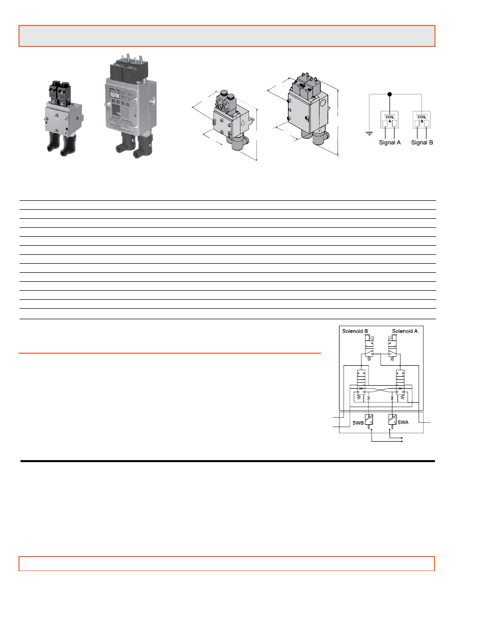
B
C
A
Crossflow
TM
Size 1
Crossflow
TM
Size 2
B
A
C
*Pressure Switches & Monitoring:
Valves without pressure switches must not
be used to control clutch/brake mechanisms
on press machinery. Valves with pressure
switches must be used in conjunction with an
external monitoring device to assist with OSHA
compliance (Ref. 1910.217).
The valves on this page do not have a built-in
monitor, and must only be used in conjunction
with an external monitoring system. Such
monitoring system must be capable of inhibiting
the operation of the valve in the event of a
failure within the valve.
* Non-monitored
Size 1 & 2
To customer’s external monitor
Series 35 Crossflow
TM
Double Valves with
Pressure Switches*
Valve Response Time (msec) = M + F • V
See page 18 for response time values.
STANDARD SPECIFICATIONS: For valves on this page.
Pilot Solenoids: Two, rated for continuous duty.
Standard Voltages: 100-110 volts, 50 Hz; 100-120 volts, 60 Hz;
24 volts DC; 110 volts DC. For other voltages, consult ROSS.
Power Consumption:
Size 1: Each solenoid, 12 VA maximum inrush, 9.8 VA maximum
holding on 50 or 60 Hz; 7.5 watts nominal on DC.
Size 2: Each solenoid, 8.5 VA maximum inrush, 8.5 VA maximum
holding on 50 or 60 Hz; 6 watts maximum on DC.
Electrical Connections: Uses two cord-grip connectors at solenoids
(order separately).
Size 1: DIN 43650 Form B connector P/N 266K77.
Size 2: Din 43650 Form A connector P/N 937K87.
Ambient Temperature: 40° to 120°F (4° to 50°C).
Media Temperature: 40° to 175°F (4° to 80°C).
Flow Media: Filtered air; 5 micron recommended.
Inlet Pressure: 40 to 100 psig (2.8 to 7 bar).
CAUTION: If the system must be reset, electrical signals to both
solenoids must be removed to prevent the machine from immediately
recycling and producing a potentially hazardous condition.
IMPORTANT NOTE: Please read carefully and thoroughly all of the CAUTIONS on the inside back cover.