Lincoln Electric LTW2 LEARNING TO STICK WELD User Manual
Page 10
7
LEARNING TO STICK WELD
Hardfacing of Idler and Roller (Metal to Metal Wear)
A very common application of hardfacing for metal to metal wear is
the hardfacing of idlers and rollers and the rails that ride on these
rollers and idlers.
The reason for hardfacing these parts is primarily monetary. A few
dollars worth of electrode will completely build up a roller or idler, and
the hard surface will outlast several times the normal life or such
rollers and idlers.
If the below procedure is followed, it is not even necessary to remove
the grease bearing while welding. This will save a lot of time.
1. The roller (or idler) is inserted on a piece of pipe that is resting on
two sawbucks. This enables the operator to turn it while welding.
2. Use Wearshield™ BU electrodes, 5/32" (4.0mm) at 175 amps or
3/16" (4.8mm) at 200 amps.
3. Weld across the wearing surface. Do not weld around.
4. Keep the roller (or idler) cool by quenching with water, and by
stopping the welding periodically. This will prevent shrinking of
the roller (or idler) on the grease bearing.
5. Build up to dimension. The weld metal deposited by
Wearshield™ BU electrode is often so smooth that machining or
grinding is not necessary.
NOTE: The quenching of the roller (or idler) has another purpose: it increases
the hardness — and thus the service life — of the deposit.
The hardfacing of the rails is a lot easier:
1. Place the rails with the side that rides on the rollers and idlers
upwards.
2. Use Wearshield™ BU electrodes, 5/32" (4.0mm) at 175 amps or
3/16" (4.8mm) at 200 amps.
3. Build up to size.
4. Do not quench. This will make the deposit slightly softer than the
deposit on the idlers and rollers. That means that the wear will
primarily be on the rails, which are a lot easier and less time-
consuming and cheaper to build up.
NOTE: The same electrode — Wearshield™ BU — will give the operator two
desired hardnesses, just by a difference in cooling rate, making it possible
to put the hardest deposit on the most expensive parts.
NOTE: The outside of the rails (the side that comes in contact with the ground)
should be surfaced with Wearshield™ ABR, since this side has Metal to
Ground wear.
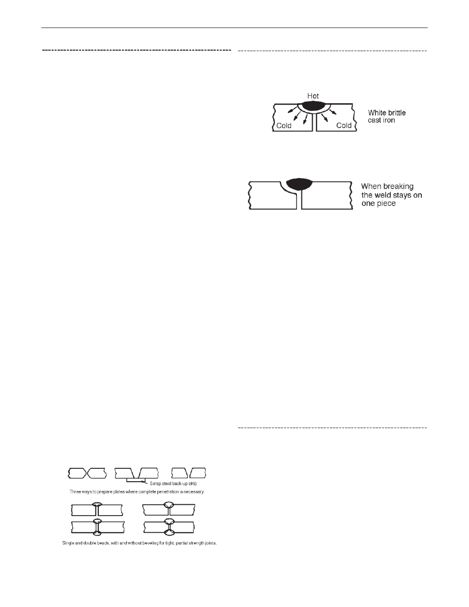
Welding Cast Iron
When welding on a piece of cold cast iron, the tremendous heat from
the arc will be absorbed and distributed rapidly into the cold mass.
This heating and sudden cooling creates WHITE, BRITTLE cast iron in
the fusion zone.
This is the reason why welds in cast iron break. Actually, one piece of
the broken cast iron has the entire weld on it, and the other piece has
no weld on it.
In order to overcome this, the welding operator has two choices:
1.
Preheat the entire casting to 500-1200°F. (260-649°C). If the
cast iron is hot before welding, there will be no sudden chilling
which creates brittle white cast iron. The entire casting will cool
slowly.
2. Weld 1/2" (12.5mm) at a time, and not weld at that spot again
until the weld is completely cool to the touch.
In this way, no large amount of heat is put into the mass.
If you have no way of preheating large castings, you’ll probably find it
easier to use the second of the two methods discussed above.
However, smaller castings can easily be preheated before welding by
using a forge, stove, fire, or Arc Torch.
When using the 1/2" (12.5mm) at a time method, it is recommended
to start 1/2" (12.5mm) away from the previous bead and weld into the
previous bead (backstepping).
After welding Cast Iron, protect the casting against fast cooling. Put it
in a sand (or lime) box.
If sand or lime is not available, cover it with sheet metal or any other
non-flammable material that will exclude drafts and retain heat.
Cast Iron Plate Preparation
Wherever practical, the joint to be welded should be “veed” out by
grinding or filing to give complete penetration. This is especially
important on thick castings where maximum strength is required. In
some instances, a back-up strip may be used and plates may be
gapped 1/8" (3.2mm) or more.
On sections where only a sealed joint is required and strength is not
important, the joint may be welded after slightly veeing out the seam
as shown.