3 lan connection, Figure 4-15: dvi connector – IEI Integration IMB-H610A User Manual
Page 77
IMB-H610 Mic ro -ATX Mo th e rb o a rd
P a g e 62
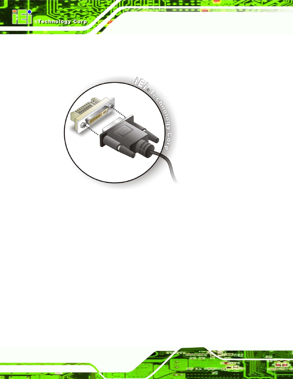
S te p 3:
Insert the DVI-I connector. Once the connectors are properly aligned with the
male connector, insert the male connector from the digital display device into the
female connector on the IMB-H610. See Figure 4-15.
Figure 4-15: DVI Connector
S te p 4:
Secure the connector. Secure the DVI-I connector from the digital display
device to the external interface by tightening the two retention screws on either
side of the connector.
4.6.3 LAN Co n n e c tio n
There are two external RJ-45 LAN connectors. The RJ-45 connectors enable connection
to an external network. To connect a LAN cable with an RJ-45 connector, please follow
the instructions below.
S te p 1:
Locate the RJ-45 connectors. The locations of the USB connectors are shown
in Chapter 3.
S te p 2:
Align the connectors. Align the RJ-45 connector on the LAN cable with one of
the RJ-45 connectors on the IMB-H610. See Figure 4-16.