3 dimm installation, Figure 4-7: dimm installation – IEI Integration IMB-H610A User Manual
Page 69
IMB-H610 Mic ro -ATX Mo th e rb o a rd
P a g e 54
S te p 4:
Secure the cooling kit by fastening the four retention screw of the cooling kit.
S te p 5:
Connect the fan cable. Connect the cooling kit fan cable to the fan connector
on the IMB-H610. Carefully route the cable and avoid heat generating chips and
fan blades.
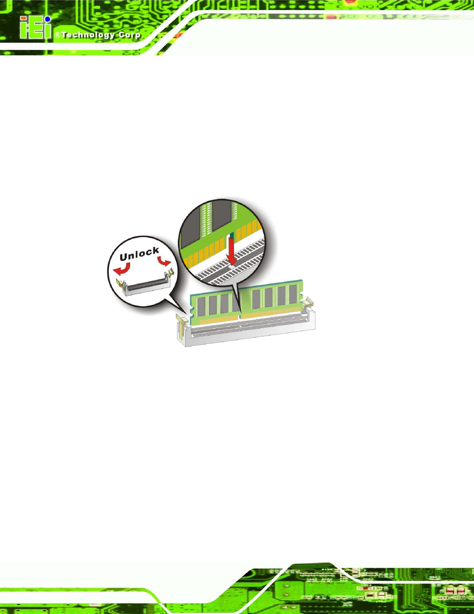
4.3.3 DIMM In s ta lla tio n
To install a DIMM, please follow the steps below and refer to Figure 4-7.
Figure 4-7: DIMM Installation
S te p 1:
Open the DIMM socket handles. Open the two handles outwards as far as
they can. See Figure 4-7.
S te p 2:
Align the DIMM with the socket. Align the DIMM so the notch on the memory
lines up with the notch on the memory socket. See Figure 4-7.
S te p 3:
Insert the DIMM. Once aligned, press down until the DIMM is properly seated.
Clip the two handles into place. See Figure 4-7.
S te p 4:
Removing a DIMM. To remove a DIMM, push both handles outward. The
memory module is ejected by a mechanism in the socket.