Figure 3-27: vga connector, Table 3-29: vga connector pinouts – IEI Integration IMB-H610A User Manual
Page 59
IMB-H610 Mic ro -ATX Mo th e rb o a rd
P a g e 44
CN Lo c a tio n :
CN P in o u ts :
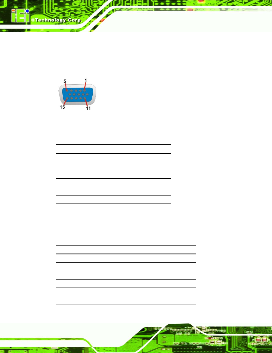
The VGA connector connects to a monitor that accepts a standard VGA input.
Figure 3-27: VGA Connector
PIN
DESCRIPTION
PIN
DESCRIPTION
1
CRT_RED
2
CRT_GREEN
3
CRT_BLUE
4
GND
5
NC
6
NC
7
NC
8
NC
9
CRT_VCC
10
CRT_PLUG#
11
NC
12
CRT_DDC_DATA
13
CRT_HSYNC
14
CRT_VSYNC
15
CRT_DDC_CLK
Table 3-29: VGA Connector Pinouts
The DVI connector connects to a monitor that supports DVI video input.
PIN
DESCRIPTION
PIN
DESCRIPTION
1
DATA2-
2
DATA2+
3
GND
4
NC
5
NC
6
DDC_CLOCK
7
DDC_DATA
8
NC
9
DATA1-
10
DATA1+
11
GND
12
NC
13
NC
14
VCC
This manual is related to the following products: