3 external interface panel connectors, 2 internal peripheral connectors, 1 atx power connector – IEI Integration IMB-H610A User Manual
Page 32: Nternal, Eripheral, Onnectors, Table 3-1: peripheral interface connectors, Table 3-2: rear panel connectors
IMB-H610 Mic ro -ATX Mo th e rb o a rd
P a g e 17
Co n n e c to r
Typ e
La b e l
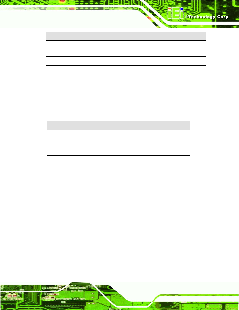
System fan connectors
3-pin wafer
SYS_FAN1,
SYS_FAN2
TPM connector
20-pin header
TPM
USB connectors
8-pin header
USB45, USB67,
USB89
Table 3-1: Peripheral Interface Connectors
3.1.3 Exte rn a l In te rfa c e P a n e l Co n n e c to rs
The table below lists the connectors on the external I/O panel.
Co n n e c to r
Typ e
La b e l
Audio connector
Audio jack
A_JACK1
Ethernet and USB connectors
RJ-45, USB
LAN1_USB01,
LAN2_USB23
Keyboard/Mouse
Dual PS/2
KB_MS
RS-232 serial port connector
DB-9 male
COM12
VGA and DVI connector
15-pin female,
24-pin header
DVI+CRT
Table 3-2: Rear Panel Connectors
3.2 In te rn a l P e rip h e ra l Co n n e c to rs
The section describes all of the connectors on the IMB-H610.
3.2.1 ATX P o we r Co n n e c to r
CN La b e l:
ATX
CN Typ e :
24-pin ATX (2x12)
CN Lo c a tio n :
CN P in o u ts :