Figure 3-24: audio connector, Table 3-23: audio connector pinouts – IEI Integration IMB-H610A User Manual
Page 55
IMB-H610 Mic ro -ATX Mo th e rb o a rd
P a g e 40
CN Lo c a tio n :
CN P in o u ts :
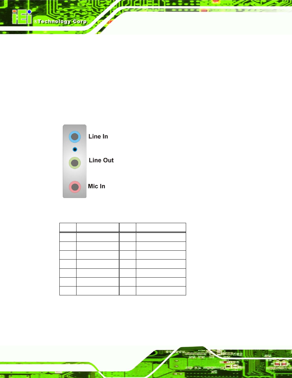
The audio jacks connect to external audio devices.
Line In port (Light Blue): Connects a CD-ROM, DVD player, or other audio
devices.
Line Out port (Lime): Connects to a headphone or a speaker. With
multi-channel configurations, this port can also connect to front speakers.
Microphone (Pink): Connects a microphone.
Figure 3-24: Audio Connector
PIN
DESCRIPTION
PIN
DESCRIPTION
1
GND
2
MIC1_L
3
GND
4
JD_MIC
5
MIC1_R
6
LOUT
7
GND
8
JD_FRONT
9
ROUT
10
LINL
11
GND
12
JD_LINE
13
LINL
Table 3-23: Audio Connector Pinouts
This manual is related to the following products: