10 lvds backlight inverter connector, Figure 3-12: backlight inverter connector location, Table 3-10: lvds connector pinouts – IEI Integration HYPER-KBN User Manual
Page 36
HYPER-KBN
P a g e 24
Pin
Description
Pin
Description
1
GND
2
GND
3
DP0_TX0P
4
DP0_TX0N
5
DP0_TX1P
6
DP0_TX1N
7
DP0_TX2P
8
DP0_TX2N
9
DP0_TX3P
10
DP0_TX3N
11
NC
12
NC
13
GND
14
GND
15
DP0_AUXN
16
DP0_AUXP
17
VCC_LCD
18
VCC_LCD
19
VCC_LCD
20
VCC_LCD
Table 3-10: LVDS Connector Pinouts
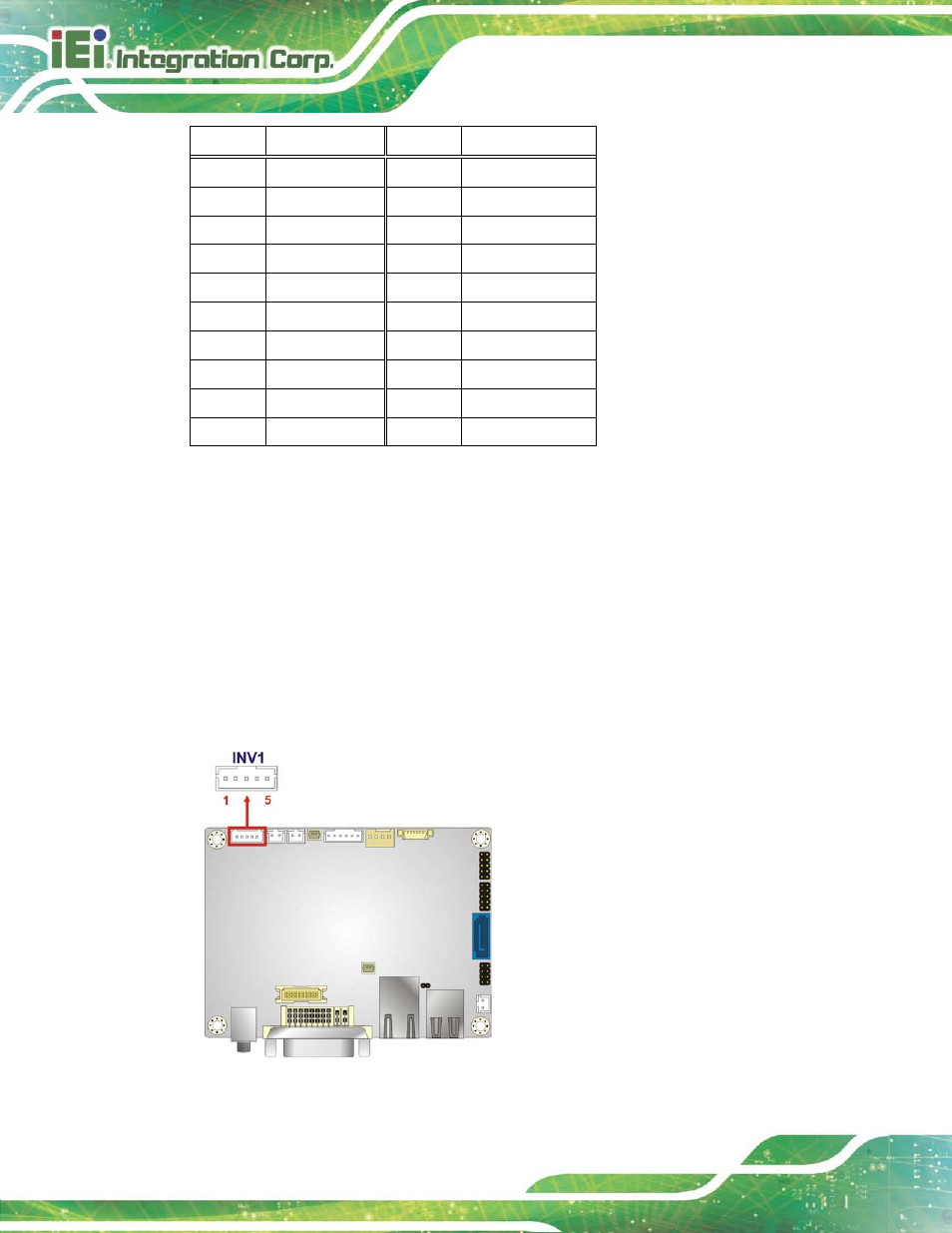
3.2.10 LVDS Ba c klig h t In ve rte r Co n n e c to r
CN La b e l:
INV1
CN Typ e :
5-pin wafer
CN Lo c a tio n :
CN P in o u ts :
The backlight inverter connector provides power to an LCD panel.
Figure 3-12: Backlight Inverter Connector Location
See also other documents in the category IEI Integration Hardware:
- SPCIE-5100DX (180 pages)
- SPCIE-C2060 v1.01 (200 pages)
- SPCIE-C2060 v2.12 (212 pages)
- SPCIE-C2160 (204 pages)
- SPCIE-C2260-i2 (217 pages)
- ROCKY-3786 v4.0 (175 pages)
- ROCKY-3786 v4.10 (147 pages)
- PCIE-Q350 v1.00 (272 pages)
- PCIE-Q350 v1.12 (250 pages)
- PCIE-Q350 v1.20 (250 pages)
- PCIE-Q350 v1.30 (213 pages)
- PCIE-Q57A (159 pages)
- PCIE-G41A2 (151 pages)
- PCIE-Q670 v1.03 (206 pages)
- PCIE-Q670 v2.00 (205 pages)
- PCIE-H610 (181 pages)
- PCIE-Q870-i2 (217 pages)
- IOWA-LX-600 (159 pages)
- PCISA-945GSE v1.01 (207 pages)
- PCISA-945GSE v1.10 (190 pages)
- PCISA-9652 v1.00 (232 pages)
- PCISA-9652 v1.01 (232 pages)
- PCISA-PV-D4251_N4551_D5251 (145 pages)
- PICOe-945GSE (197 pages)
- PICOe-GM45A (198 pages)
- PICOe-PV-D4251_N4551_D5251 v1.00 (154 pages)
- PICOe-PV-D4251_N4551_D5251 v1.10 (154 pages)
- PICOe-PV-D4251_N4551_D5251 v1.11 (155 pages)
- PICOe-B650 (156 pages)
- PICOe-HM650 (174 pages)
- SPXE-14S (3 pages)
- SPXE-9S v1.00 (5 pages)
- SPXE-9S v1.1 (6 pages)
- SPE-9S v1.00 (4 pages)
- SPE-9S v1.1 (5 pages)
- SPE-6S (3 pages)
- SPE-4S (4 pages)
- PE-6SD3 (4 pages)
- PE-6SD2 v4.0 (4 pages)
- PE-6SD2 v2.10 (3 pages)
- PE-6SD (3 pages)
- PE-6S3 v1.0 (2 pages)
- PE-6S3 v4.0 (4 pages)
- PE-6S2 (4 pages)