3 external interface panel connectors, 2 internal peripheral connectors, 1 at/atx mode select switch – IEI Integration HYPER-KBN User Manual
Page 28: Nternal, Eripheral, Onnectors, Table 3-1: peripheral interface connectors, Table 3-2: rear panel connectors
HYPER-KBN
P a g e 16
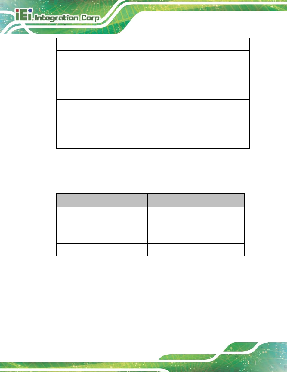
LVDS backlight inverter connector
5-pin wafer
INV1
Power button connector
2-pin wafer
PWR_BTN1
Reset button connector
2-pin wafer
RST_BTN1
RS-232 serial port connector
10-pin header
COM1
SATA 6Gb/s drive connector
7-pin SATA connector
SATA1
SATA power connector
2-pin wafer
SATA_PWR1
SPI Flash connector
6-pin wafer
SPI1
System fan connector
4-pin wafer
FAN1
USB connector
8-pin header
USB2
Table 3-1: Peripheral Interface Connectors
3.1.3 Exte rn a l In te rfa c e P a n e l Co n n e c to rs
The table below lists the connectors on the external I/O panel.
Connector
Type
Label
DVI connector
24-pin female
DVI_1
LAN connector
RJ-45
LAN1
Power connector
DC power jack
PWR_CON1
USB connector
USB 3.0
USB1
Table 3-2: Rear Panel Connectors
3.2 In te rn a l P e rip h e ra l Co n n e c to rs
The section describes all of the connectors on the HYPER-KBN.
3.2.1 AT/ATX Mo d e S e le c t S witc h
CN La b e l:
J_ATX_AT1