Step two locked position unlocked position, Step one, Step three step four – WEATHER GUARD 1200 User Manual
Page 3
Page 3 of 8
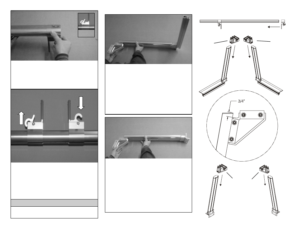
The ladder stops are designed to slide the
entire length of the cross member. Once
in the desired location, lock ladder stops
in place by lifting up on the lever. To un-
lock, push down on the lever. For purpose
of installation position them two feet from
either end.
STEP TWO
Locked
Position
Unlocked
Position
To Lock
To Unlock
Do not operate vehicle with ladder
stops in the unlocked position.
IMPORTANT!
Slide the triangle brackets, Part C, into the
driver side front leg, Part D, and passen-
ger side front leg, Part E, from the top.
The 5/16-18 nuts are to face towards the
rail side of the leg. Using the triangle di-
mension diagram to the right as a guide,
position the triangle brackets 3/4" from the
top of the leg. Tighten the 5/16-18 fasten-
ers to 15 foot pounds of torque.
Holding the ladder stops, Part A, upside
down and in the unlocked position, slide
them onto each end of the cross member,
Part B. Repeat the process for the other
cross member.
STEP ONE
Slide the triangle brackets, Part C, into
each of the universal rear legs, Part F, from
the top. Create a driver side and passen-
ger side rear leg by facing the 5/16-18 nuts
one direction on a leg and the other direc-
tion on the other. Using the triangle dimen-
sion diagram to the right as a guide,
position the triangle brackets 3/4" from the
top of the leg. Tighten the 5/16-18 fasten-
ers to 15 foot pounds of torque.
STEP
THREE
STEP FOUR
PART B
PART A
PART D
PART E
PART F
PART F
Rail Side
Triangle
Dimension
Diagram
Rail Side
5/16-18
Nuts
Face
towards
rail side
5/16-18 nuts
face in one
direction
Drivers
Side
Passenger
Side
5/16-18
Nuts
Face
towards
rail side
PART C
PART C
PART C
PART C
Unlocked
Position