Warner Electric MTB II User Manual
Page 6
6
Warner Electric • 800-825-9050
819-0342
Since the armature and magnet faces are the
only tension brake components which sustain
wear, replaceable faces are offered for both, to
maximize brake life. The following instructions
deal with wear assessment and friction face
replacement.
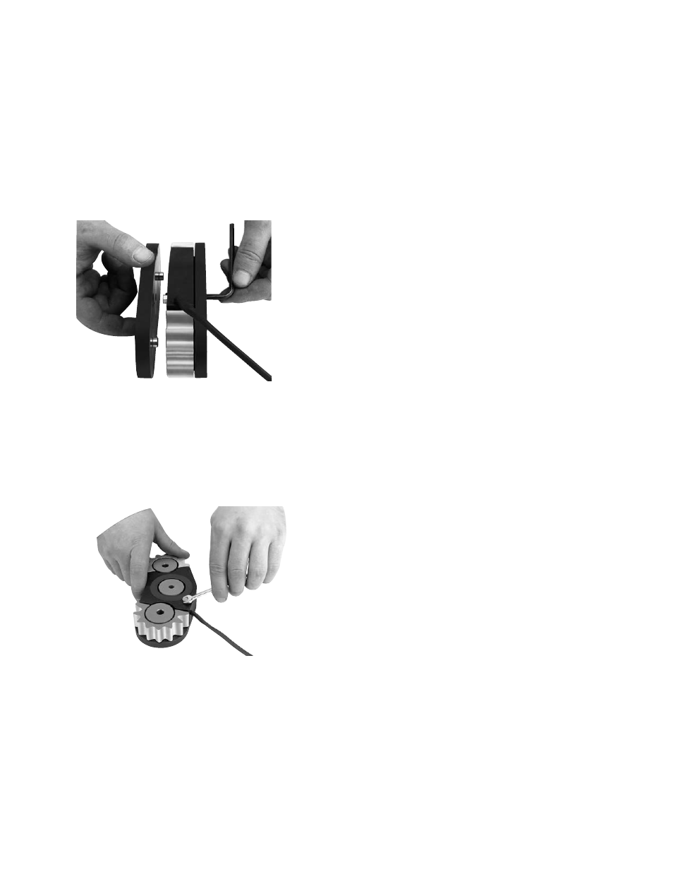
Replacement of Friction Pads
Remove the old pads from the magnets.
(Figure 17)
Figure 17
If the magnets are supplied with electronic wear
indicators, replace the hexagon brass contacts
(Warner Electric part no. 274-1029) on each
magnet. Tighten to 6-8 in. lb. torque. Attach the
new pads to the magnets. Tighten each screw
to 7-9 ft. lbs. torque. (Figure 18)
Figure 18
Assemble and Install
the Armature Assembly
Follow the previous instructions for assembly
and installation of the armature assembly.
Wear-In
Replacement of the friction faces will require a
new wear-in period as the pads seat themselves
on the armature.
With a closed-loop control system, such as
dancer or load cell control, no changes in torque
will be apparent during wear-in. The control
system will compensate for any variations.
With a manual control system, however, an
unburnished brake will produce only about 75%
of its fully burnished torque. If full torque is
required at start-up, the brake should have a
preburnish period to fully seat the magnets on
the armature to provide full torque. If this is not
possible, several torque adjustment settings will
be required during the initial hours of on line
operation. Burnishing is the process of mating
the friction surfaces of a brake that is mounted
and ready for service.
Modification of Straight Bore
Armature Carriers
The straight bore armature carrier may be
modified to accept a variety of mountings.
If a modification to the armature is required, the
modified assembly must meet the following
requirements. With the armature assembly fully
installed on the shaft:
1. Maximum radial runout of the aluminum
carrier is .008”
2. Maximum axial runout on either face is .015”
T.I.R.