Warner Electric MTB II User Manual
Page 5
5
Warner Electric • 800-825-9050
819-0342
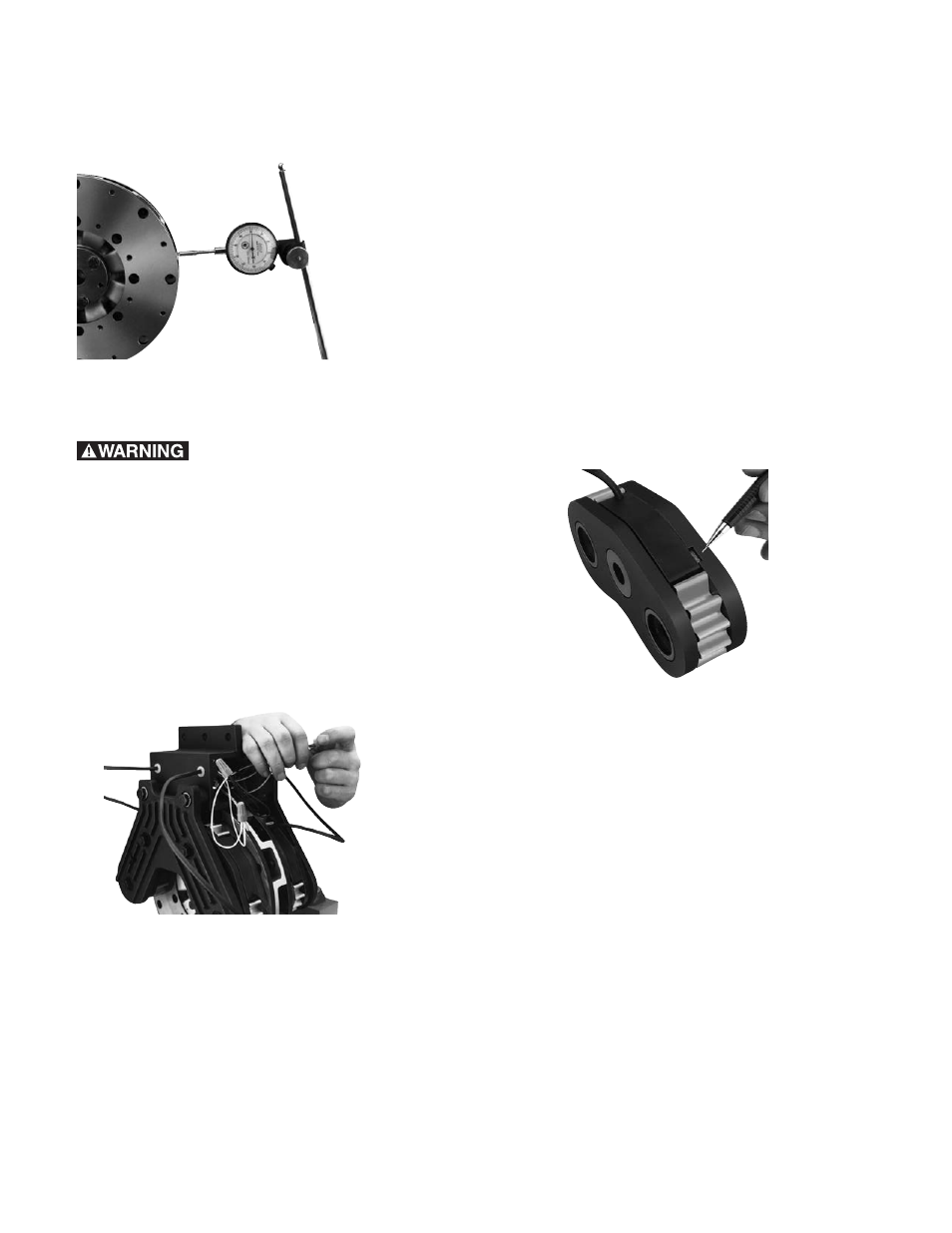
If the bore on the aluminum carrier has been
modified, the radial runout of the aluminum
carrier is not to exceed .008 inches. (Figure 14)
Figure 14
Control Connection
Contact with live wires can
cause injury or death. Be sure all power is
turned off before starting the connection
process.
Wire the magnets to the control in accordance
with the instructions included with the control.
Warner Electric offers several different systems
ranging from a simple manual control through a
roll follower system to several types of closed
loop systems. For more information, ask for
catalog P-771. (Figure 15)
Figure 15
Servicing Modular Tension Brake Friction
Surfaces Magnet Inspection
Each magnet is supplied with visual wear
indicators. When the magnet is worn to these
indicators, pad replacement is required. (Figure
16)
If the magnet is supplied with an electronic wear
indicator, a signal will be sent to the control to
indicate replacement is required.
Both the visual and electronic wear indicators
are preset to indicate replacement at 85 percent
wear out, allowing 15 percent more life for
planned maintenance.
A used armature should not be resurfaced
nor turned over to be used on the other side.
Figure 16
Rebuild Procedure
Note: When disconnecting and reconnecting
leads to the magnet, the input power must be
shut off to the control system.
Removal of the Armatures
If required, remove the armature assembly from
the shaft.
Remove the brackets and magnet carriers to
gain access to the armature(s). Remove the
armature face(s) with the armature in place, if
possible. If machine framework or components
prevent face(s) removal, the entire armature
assembly may have to be separated from the
brake hub and removed from the machine to
access the face(s).