Warner Electric MTB II User Manual
Page 2
2
Warner Electric • 800-825-9050
819-0342
Introduction
The instructions on this sheet cover installation
of all replacement components available for
modular tension brakes. These instructions are
divided into sections as designated by the
introductory headlines. Please check these
headings to locate the proper instruction for the
replacement components being installed.
Friction components, the most frequently
replaced items, are found near the end of these
instructions.
Failure to follow these
instructions may result in product damage,
equipment damage, and serious or fatal
injury to personnel.
Contents
Assembling Armature to Armature Carrier . . . . . . . .2
Installing the Armature Assembly . . . . . . . . . . . . . .3
Tapered Bushing Carrier . . . . . . . . . . . . . . . . . . . . .3
Straight Bore Carrier . . . . . . . . . . . . . . . . . . . . . . . .3
Mounting the Magnets . . . . . . . . . . . . . . . . . . . . . . .3
Adjusting the Armature Assembly . . . . . . . . . . . . . .4
Control Connection . . . . . . . . . . . . . . . . . . . . . . . . .5
Servicing Friction Surfaces . . . . . . . . . . . . . . . . . . .5
Rebuild Procedure . . . . . . . . . . . . . . . . . . . . . . . . . .5
Removal of the Armatures . . . . . . . . . . . . . . . . . . . .5
Replacement of Friction Pads . . . . . . . . . . . . . . . . .6
Assemble and Install the Armature Assembly . . . . .6
Wear-In . . . . . . . . . . . . . . . . . . . . . . . . . . . . . . . . . . .6
Modification of Straight Bore Armature Carriers . . .6
Bulk Head Mounting Brackets . . . . . . . . . . . . . . . . .7
Direct Mounting . . . . . . . . . . . . . . . . . . . . . . . . . . . .8
Universal Mounting . . . . . . . . . . . . . . . . . . . . . . . . .9
Brake Assemblies and Part Numbers . . . . . . . . . .10
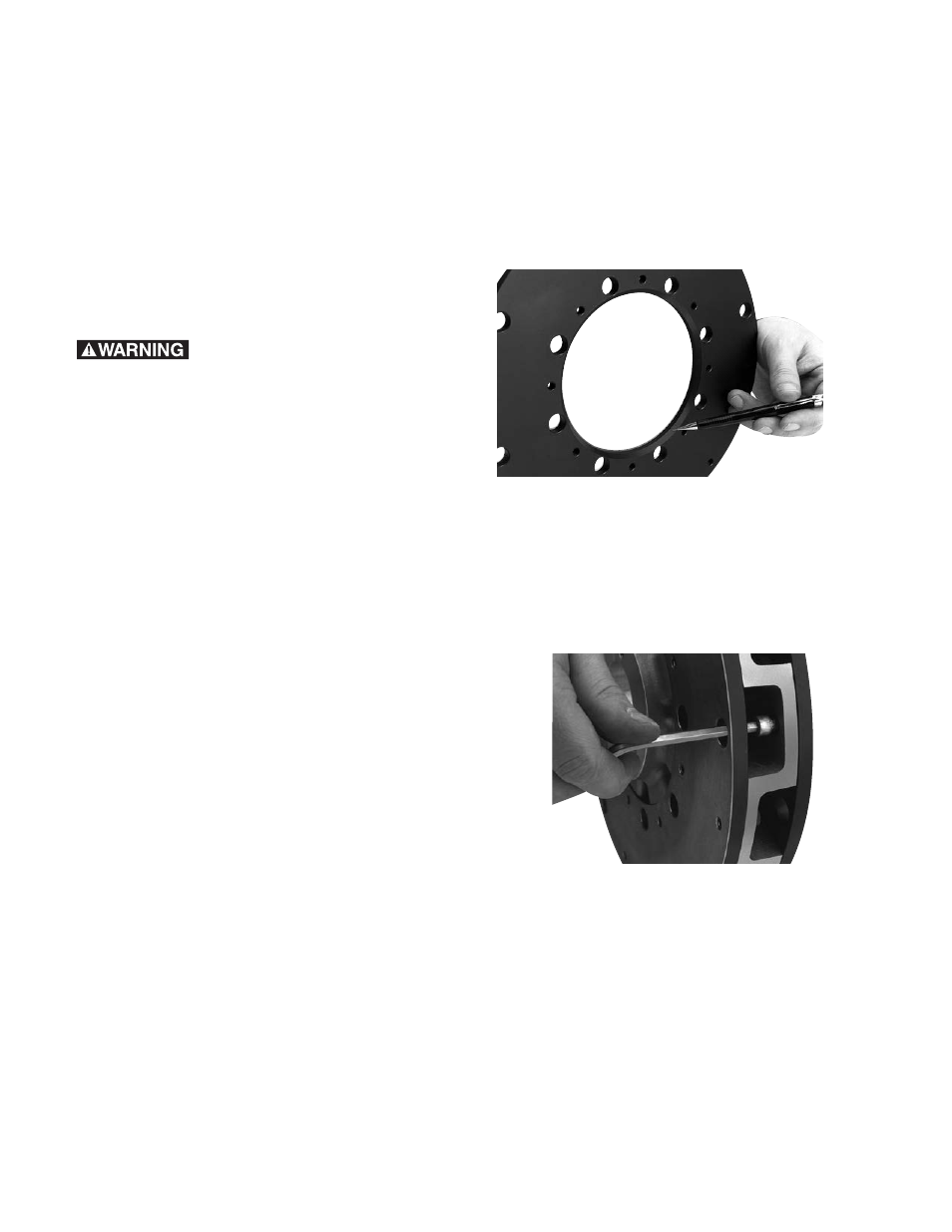
Assembling the Armature to the Armature
Carrier
The beveled edge on the inside diameter of the
armature is to be assembled facing the armature
carrier. Tighten all screws to 7-9 ft. lbs. torque.
(Figure 1)
Figure 1
Using the screws and lockwashers provided
with the armature(s), mount the armature(s) to
the armature carrier. If a single armature is used,
mount it on the appropriate side of the hub. Be
sure to allow easy access to the tapered
bushing. (Figure 3)
Figure 2