Warner Electric PCC-825, PCC-1000, PCC-1225, PCC-1525 User Manual
Page 6
6
Warner Electric • 800-825-9050
P-206 • 819-0519
D. Mounting the Armature Assembly
1. Slide the armature assembly and
customer supplied pulley, sprocket or hub
onto the shaft.
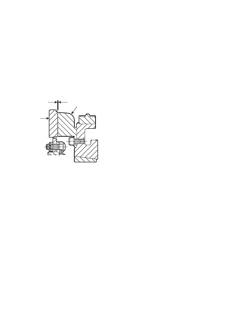
If the magnet and magnet hub assembly
has been secured to the shaft first, then
adjust the magnet's position to allow
approximately 1/32-inch between the two
faces.
Once this 1/32" gap has been set, it will be
automatically maintained throughout the life
of the unit. (See Figure 10)
2. Secure the armature assembly and
customer supplied pulley, sprocket and hub
in this position by a) retainer rings, b) set
collars, c) shoulder on the shaft, or d) any
combination of these. The best method will
depend on the characteristics of each
application.
E. Mounting the Brushholder
1. The brushholder is mounted on a bracket
which must be furnished by the customer.
The bracket must be firmly secured to pre-
vent vibration which could cause improper
contact between the brushes and collector
ring.
2. The distance from the centerline of the
shaft to the top of the brushholder should
be 5-3/4". Maintaining this distance will
assure proper spring tension on the brush-
es and maximum wear follow-up. A
detailed dimensional drawing is included
with each brushholder.
1/32-inch
Armature
Magnet
Figure 10