Tx 5.3.4 and 5.3.5 vpp, vma, eq (d30.3), Figure 18 - common mode rms voltage results – Teledyne LeCroy QPHY-SAS3 User Manual
Page 26
• M3 is the Common Mode Spectrum Mask as defined in the specification shown on a linear scale. If
the Common Mode Spectrum trace exceeds the mask the test will fail.
• F7 is the margin and is calculated as the difference between the Common Mode Spectrum trace and
the Common Mode Spectrum Mask. A cursor is placed at 0 dBmV in order to provide a visual aid
in seeing where there is positive margin.
Figure 18 - Common Mode RMS Voltage Results
In the Measure section:
• CM Offset (P1) is the common mode offset. This is measured by taking the mean of the common
mode trace. This is provided as informational only.
• CM RMS (P2) is the common mode RMS voltage. This is measured by taking the RMS of the
common mode trace. This is provided as informational only.
• Max(F5) (P3) is maximum value of the Common Mode Spectrum trace. This is provided as
informational only.
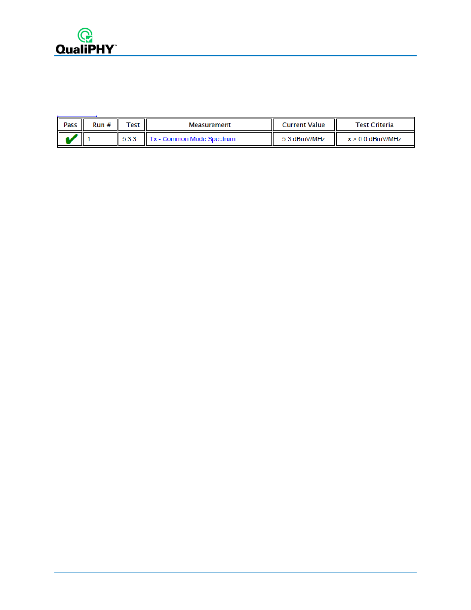
• CM Margin (P5) is the amount of margin between the Common Mode Spectrum trace and the mask.
This is measured by taking the minimum value of the difference between the Common Mode
Spectrum trace and the Common Mode Spectrum mask. This is the measured value for Tx –
Common Mode Spectrum (5.3.3). This value must be greater than 0 dBmV/MHz in order to pass
this test.
Tx 5.3.4 and 5.3.5 Vpp, VMA, EQ (D30.3)
The purpose of these tests is to verify that the peak-to-peak voltage, the voltage modulation amplitude,
and the amount of equalization are within the specification limits. These tests only apply for 1.5Gbps,
3Gbps, and 6Gbps DUTs and is not included in any of the pre-loaded configurations for 12Gbps.
However, it still can be run on 12Gbps DUTs for additional information. After the completion of the Vpp,
VMA, and EQ tests the oscilloscope is in the following configuration:
26
922545 Rev A